[0006]This object is achieved in that the grip body is constructed from at least two individual pole-grip elements, wherein a first pole-grip element is connected to the pole shaft in a form-fitting and / or force-fitting manner, such that no movement can take place, and a second pole-grip element is arranged on the first pole-grip element such that it can be displaced and secured and / or exchanged, and this therefore allows adaptation to different hand sizes.
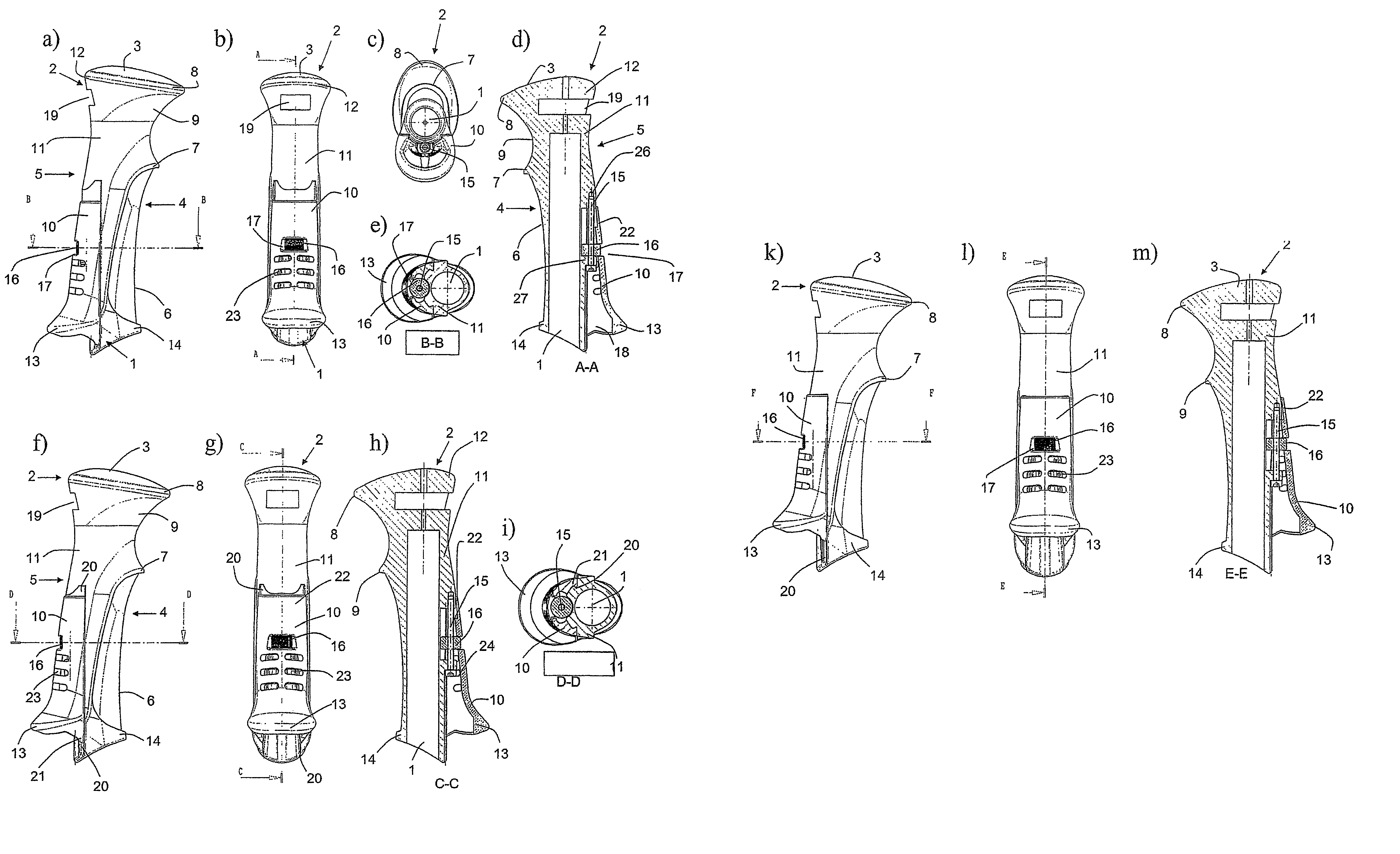
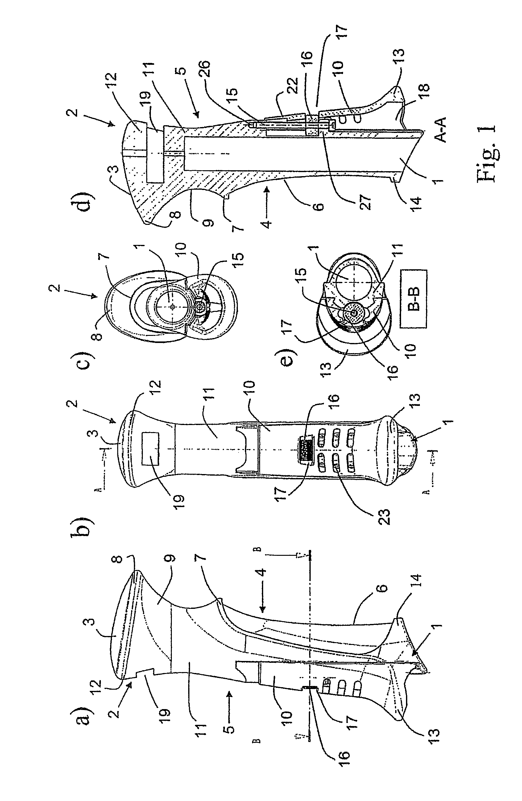
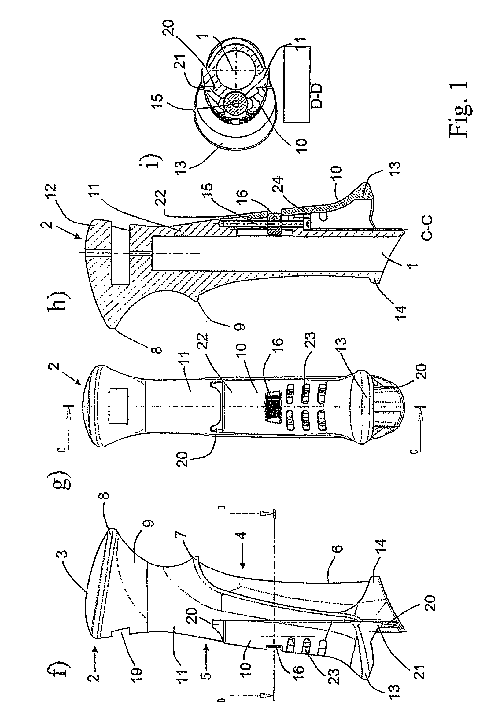
[0007]The core of the invention is thus to construct the pole grip from two elements which can be secured in different positions relative to one another. The two elements can be secured in different positions here such that adaptation to different hand sizes or to use with / without a glove is made possible. In particular it is possible to allow for even very large differences, for example to allow simultaneously for the possibility of adaptation to a child's hand and to an adult's hand. In other words, the pole grip provided is one which virtually “grows” with the user. According to a first preferred embodiment of the pole grip, the latter is characterized in that the first pole-grip element forms the head region and the forwardly directed region, and the second pole-grip element is arranged on the side which is directed rearward as seen in the movement direction. The second pole-grip element here preferably comprises the bottom, rearwardly directed terminating protrusion. The second pole-grip element preferably forms, at least in part, the rearwardly directed grip region of the pole grip. The second pole-grip element is thus essentially L-shaped, in that the second pole-grip element forms preferably both the bottom region of the rearwardly directed grip region of the pole grip, which ends up to be located in the palm of the user's hand, and the terminating protrusion which projects rearward from the rearwardly directed grip region, and at least partially engages around and / or supports the bottom edge of the user's hand. The rearwardly directed terminating protrusion is preferably formed integrally with the rearwardly directed grip region of the pole grip or formed fixedly thereon. As a result of the second grip element being adjusted in terms of height in the axial direction parallel to the pole axis, it is thus the case that both, in part, the rearwardly directed grip region of the pole grip and the rearwardly projecting terminating protrusion are displaced together. If the second pole-grip element is displaced downward, then the size of the grip can be adapted to a larger hand since the rearwardly directed terminating protrusion is displaced downward and makes space in the axial direction for a larger hand. As a result of the first pole-grip element being partially overlapped by the second pole-grip element, displacement of the second pole-grip element axially downward results in regions of the first pole-grip element being exposed and upward displacement, i.e. for adaptation to a smaller hand size, results in those regions of the first pole-grip element being covered over again, wherein, when the second pole-grip element is displaced upward, bottom regions of the first pole-grip element are exposed again. The rearwardly directed shoulder, moreover, is particularly suitable as a point of engagement for the displacement of the second pole-grip element since it is easy to grip the shoulder.
[0008]This special construction, on the one hand, has proven to be particularly straightforward in design terms and, on the other hand, it allows the largest possible adjustment range. The concept is based on the fact that, as it were, the axial position of the hand, by virtue of the position of the forefinger in the depression at the front, is defined by the first pole-grip element irrespective of the hand size. The problem with the prior-art grips, then, is that, in the case of a hand being too small for the pole grip, the bottom rear terminating protrusion, on which the bottom edge of the hand should rest when the pole is used efficiently for pushing-off purposes, is arranged at a point remote from the hand. According to the invention, then, it is precisely this bottom rear terminating protrusion which is configured to be axially adjustable, that is to say it can easily be displaced upward, virtually, from a bottom position for very large hands until it ends up to be located comfortably on the bottom edge of the user's hand and, accordingly, allows the pole to be used efficiently for pushing-off purposes and makes the pole comfortable to grip. This can be realized particularly advantageously in design terms if the second pole-grip element forms, at least in part, the rearwardly directed grip region of the pole grip.
[0014]In order for it to be possible to ensure, in the case of such a variable-fastening method, that the two elements are fastened such that they cannot be displaced relative to one another, it may prove to be advantageous, according to a preferred embodiment, if the first pole-grip element and the second pole-grip element have a toothing formation, and these toothing formations, by engaging one inside the other, enhance the axial securing action of the two elements in relation to one another and allow more or less stepless adjustability.
