Electronic device, adapter and receptacle

a technology of electronic devices and adapters, applied in the direction of coupling devices, two-part coupling devices, electrical equipment, etc., can solve the problems of accidental damage, poor signal contact phenomenon, thin cards without metallic outer casings, etc., and achieve the effect of avoiding disorientation

Active Publication Date: 2012-02-28
IND TECH RES INST
View PDF11 Cites 3 Cited by
  • Summary
  • Abstract
  • Description
  • Claims
  • Application Information

AI Technical Summary

Benefits of technology

[0007]An electronic device is introduced herein capable of avoiding disorientation when connecting with the receptacle and a poor contact.
[0008]An adapter is introduced herein capable of combining with the electronic device and enhancing a compatibility property.
[0014]In summary, an electronic device according to an embodiment of the disclosure has a stub and / or a locked hole, thereby preventing disorientation and ensuring a reliable contact with the receptacle. An adapter according to an embodiment of the disclosure provides elastic terminals capable of enhancing a compatibility property of the electronic device. The receptacle according to an embodiment of the disclosure employs two types of elastic terminals, hence a preferable compatibility property is achieved.

Problems solved by technology

However, thin cards are not equipped with the metallic outer casing.
Accordingly, when thin cards purchased on the market today are plugged into a female receptacle, shaking typically results and causes a poor signal contact phenomenon.
When storing or carrying the thin card 20, the terminal 22 protruding from a surface of the thin card body comes easily into collision or friction with external objects, thereby causing accidental damages.

Method used


Image

  • Electronic device, adapter and receptacle
  • Electronic device, adapter and receptacle
  • Electronic device, adapter and receptacle

Examples


Embodiment Construction

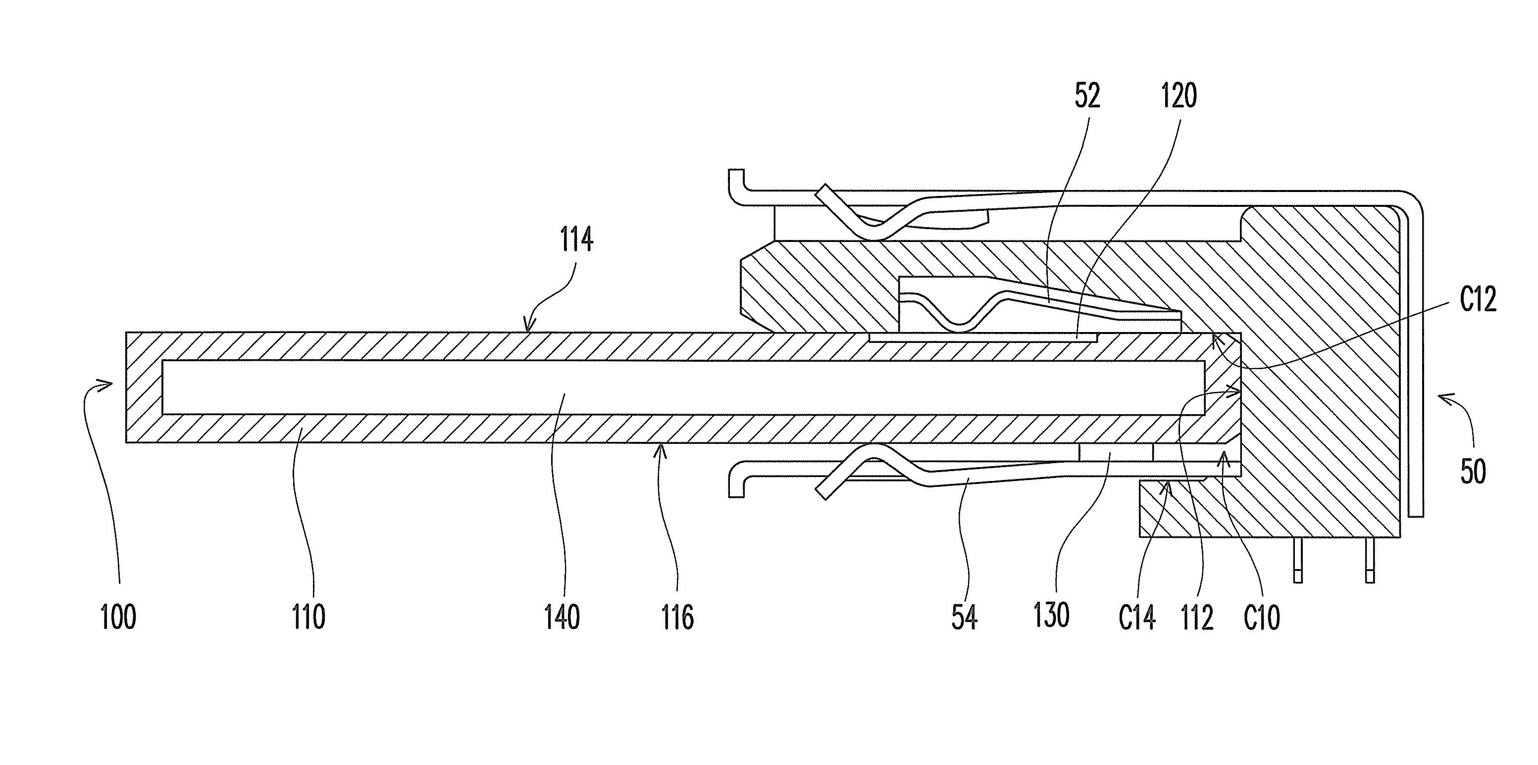
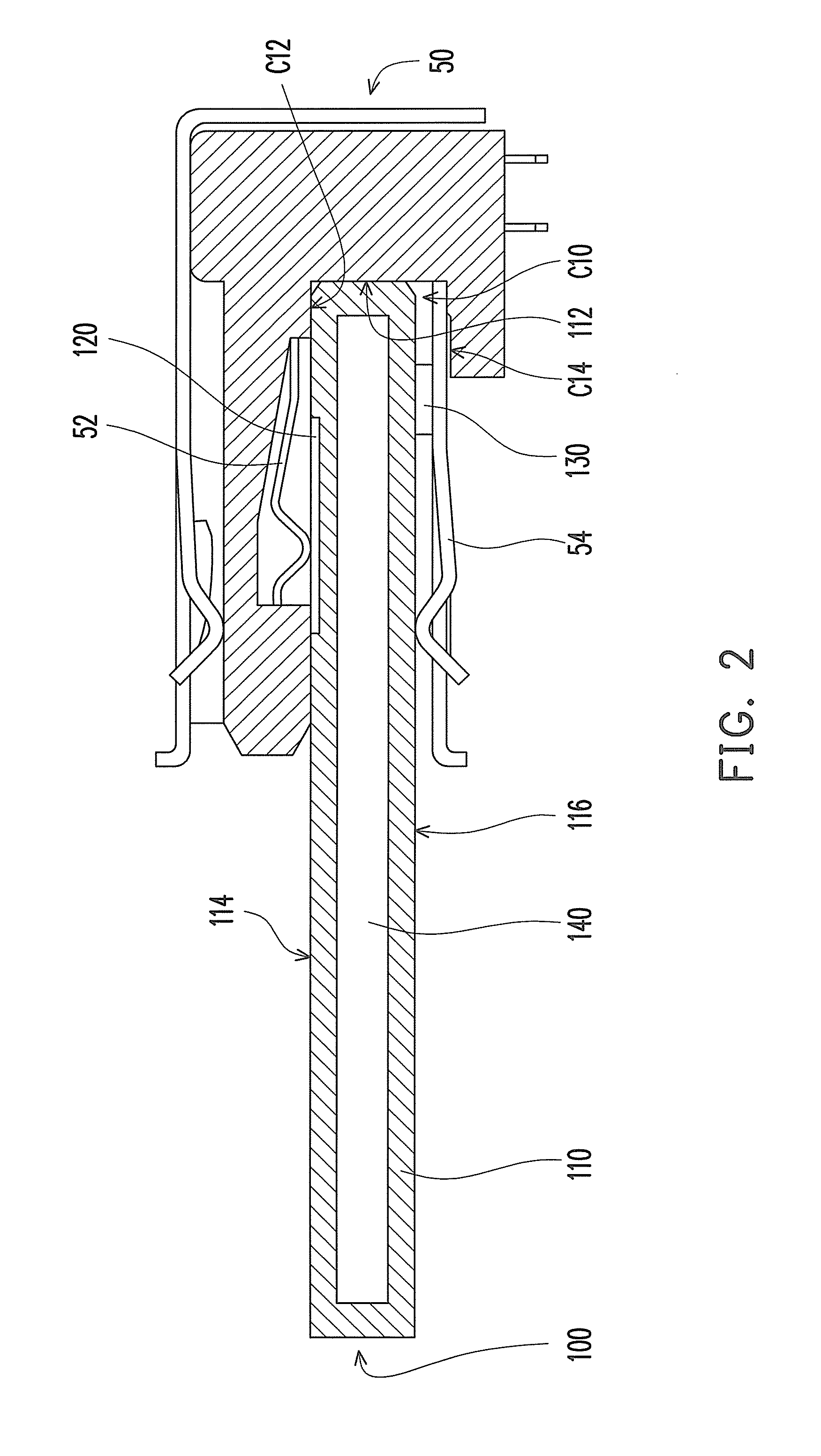
[0032]FIG. 2 is a schematic assembly view of an electronic device and a receptacle according to an exemplary embodiment of the disclosure. Referring to FIG. 2, an embodiment provides an electronic device 100 including a card body 110, a plurality of terminals 120 (only one terminal 120 is depicted in FIG. 2), and at least one sub 130. The card body 110 has a front edge 112, a first surface 114, and a second surface 116 opposite to the first surface. The terminals 120 are arranged on the first surface 114 and near the front edge 112. The stub 130 is disposed on the second surface 116 and near the front edge 112. A receptacle 50 has a cavity C10. A top wall of the cavity C10 has a plurality of terminals 52 thereon. Moreover, a bottom wall C14 of the cavity C10 has at least one orientation spring 54 thereon, or the bottom wall C14 has no orientation spring 54 thereon. After the electronic device 100 is plugged into the cavity C10 of the receptacle 50, the bottom wall C14 of the cavity ...


PUM


Abstract

An electronic device, an adapter and a receptacle are provided. The electronic device includes a card body, a plurality of first and second terminals, and at least one stub. The card body has a front edge, a first surface and a second surface opposite to the first surface. The first terminals are between the first terminals and the front edge. The stub is disposed on the second surface and near the front edge. The adapter includes a body and a plurality of elastic terminals. The body has an accommodating portion for accommodating an electronic device. One ends of the elastic terminals are fixed to the body. When the electronic device is accommodated at the accommodating portion, a plurality of flat terminals of the electronic device are outside of the accommodating portion, and another ends of the elastic terminals are against the flat terminals correspondingly.

Description

CROSS-REFERENCE TO RELATED APPLICATION[0001]This application claims the priority benefit of U.S. provisional application Ser. No. 61 / 310,706, filed on Mar. 5, 2010 and Taiwan application serial no. 99124178, filed Jul. 20, 2010. The entirety of each of the above-mentioned patent applications is hereby incorporated by reference herein and made a part of specification.BACKGROUND OF THE DISCLOSURE[0002]1. Field of Invention[0003]The disclosure relates to an electronic device, an adapter, and a receptacle, and more particularly to an electronic device, an adapter, and a receptacle adapted for a Universal Serial Bus (USB) specification.[0004]2. Description of Related Art[0005]Nowadays, more and more manufacturers are investing in thin card-related product development and manufacturing. USB thin card products include the common Bluetooth module and the Global Positioning System (GPS) module, as well as the thin memory card equipped with a flash memory. Currently, the standard USB male plu...

Claims


Application Information

Patent Timeline
Patent Type & Authority Patents(United States)
IPC IPC(8): H01R24/00
CPCH01R12/00H01R24/00H01R27/00
Inventor LIU, CHIH-YUANLIN, CHIEN-HONGWEN, YI-LUNSUN, GILBERT
Owner IND TECH RES INST
Why Eureka
Try Eureka