Calibration of a radiometric optical monitoring system used for fault detection and process monitoring

a radiometric optical monitoring and fault detection technology, applied in the field of radiometric calibration of spectroscopy equipment, can solve the problems of affecting the implementation of these designs, affecting the recording spectrum, and affecting the quality of the measurement, etc., and achieve the effect of variable throughpu

Active Publication Date: 2012-02-28
VERITY INSTR
View PDF17 Cites 38 Cited by
  • Summary
  • Abstract
  • Description
  • Claims
  • Application Information

AI Technical Summary

Benefits of technology

[0010]Next, the response of reference spectrograph is used as a secondary standard for calibrating one or more production spectrographs to a separate light source. The reference spectrograph and a production spectrograph receive spectral radiation from a production reference light source and generate separate outputs in response to the light. Optimally, the spectral bandwidth of the production reference light source should be similar to the spectral range of a production spectrograph. This light source need not be a calibration light source, and the precise spectral intensities of the light need not be known because that information will be accurately measured by the reference spectrograph. It is expected that the reference and production spectrographs receive light from the production reference light source simultaneously, thereby removing the requirement for a stable light source of known intensity. Alternatively, if the production reference light source is relatively stable, the output from the reference and production spectrographs may be acquired sequentially. The uncalibrated output from the production spectrograph is compared to the calibrated output produced by the reference spectrograph. Based on that comparison, a set of production output correction coefficients can be derived for the production spectrograph to be used in conjunction with an output algorithm for adjusting the raw output to the known intensities of the production reference light source. Once calibrated, a production spectrograph will produce quantitative spectroscopy measurements for any light source within its spectral range (similarly to the reference spectrograph). Note that the calibration of the production spectrograph is accomplished without using a standard calibration light source. Additional production spectrographs may be calibrated in a similar manner. In so doing, the present invention enables comparisons of spectra generated on different spectrographs and, even more importantly, facilitates quantitative comparisons of results obtained from different process chambers using different, but calibrated, spectrographs.
[0012]In accordance with other embodiments of the present invention, the production spectrograph and optical coupling system can be calibrated together as a single unit. In so doing, the response of the spectrograph can be calibrated for any changes in the throughput that may result from the addition of the optical coupling system. Here again, all air passages in the optical path should be purged of oxygen or the air circulated to avoid the accumulation of ozone in the optical path. If an optical fiber is used with the coupling system, the fiber should be arranged identically for calibration as it will be configured with the production chamber. If the production configuration is not known during the initial calibration stage, then the arrangement of optical fiber used for the calibration can be recorded and sent to the fabrication facility with the calibration data. In that way, the production operator can configure the arrangement of the optical fiber with the production chamber identical to the arrangement during the initial calibration stage.

Problems solved by technology

There exists a difficulty associated with the implementation of these designs, however.
The difficulty is that the recorded spectrum is influenced by factors other than the properties of the light emitted by the plasma.
Another problem is that the window into the plasma chamber may become coated with contaminants which absorb or scatter an unknown fraction of the light.
Another problem is that the efficiency of the rest of the coupling system may change in response to unavoidable perturbations or variations in the setup.
It is often necessary to take special steps to maintain the transmission properties of the window because of the tendency for the inside surface to become contaminated or etched due to the action of the reactive gases in the chamber.
Another potential source of instability is absorption of light by oxygen or ozone in the air path.
Fiber optic coupling presents special challenges for a stable coupling system.
First, fiber optics transmission is subject to degradation upon exposure to UV radiation.
The second challenge in using fiber optics is that fiber optic transmission may be affected by changes in the position of the fiber, regardless of where the changes occur along its length.
A light source of known and constant output is difficult and expensive to realize, especially over a broad wavelength range that includes ultraviolet light below 300 nm in wavelength.
Furthermore, all light sources, even NIST bulbs, are prone to drift as a function of the operating time (see for instance, the intensity drift of an exemplary NIST calibration light source in FIG. 13).
Minute differences in fiber optic bundle transmission is the single largest perturbation that limits the precision that can be achieved, even with fiber optic bundles that are new and manufactured to be identical.
The first and most difficult part is performed at the point of manufacture of the spectrometer.
A small change in the bend radius of an optical fiber or fiber optic bundle may cause the throughput to change by an amount which is significant.
It does not, however, account for any effects on optical transmission due to the plasma chamber.
Since each and every spectrograph coupled to a process chamber in a facility would require calibration to the local primary standard, the aforementioned benefits of a reference spectrograph would be unrealized.

Method used


Image

  • Calibration of a radiometric optical monitoring system used for fault detection and process monitoring
  • Calibration of a radiometric optical monitoring system used for fault detection and process monitoring
  • Calibration of a radiometric optical monitoring system used for fault detection and process monitoring

Examples


Embodiment Construction

Element Reference Number Designations

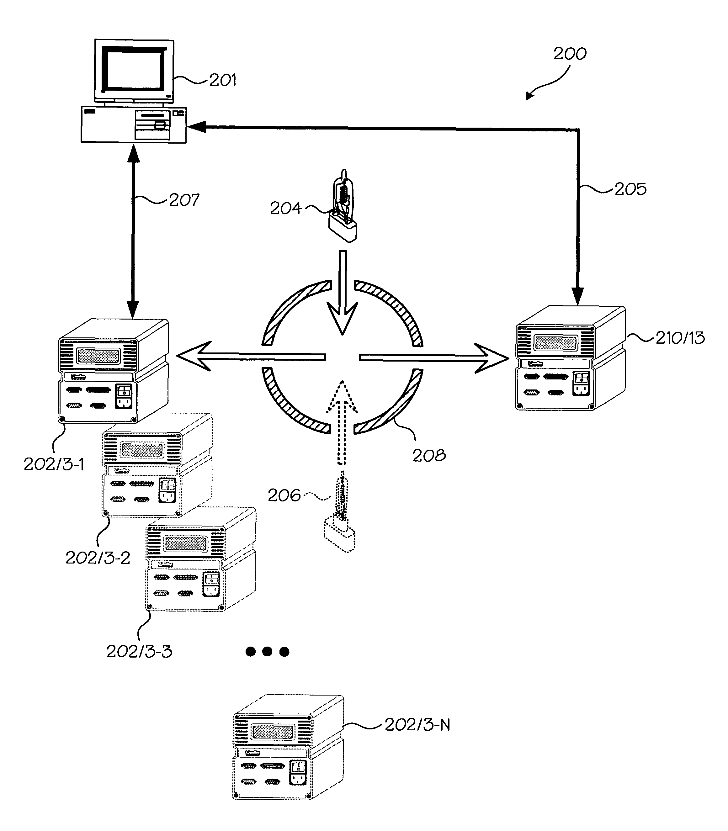
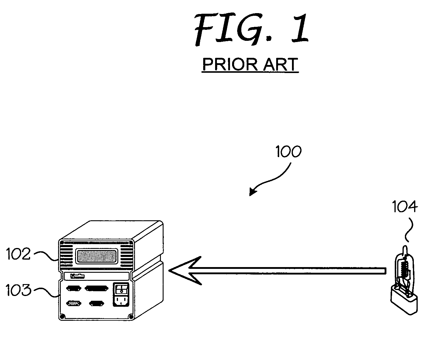
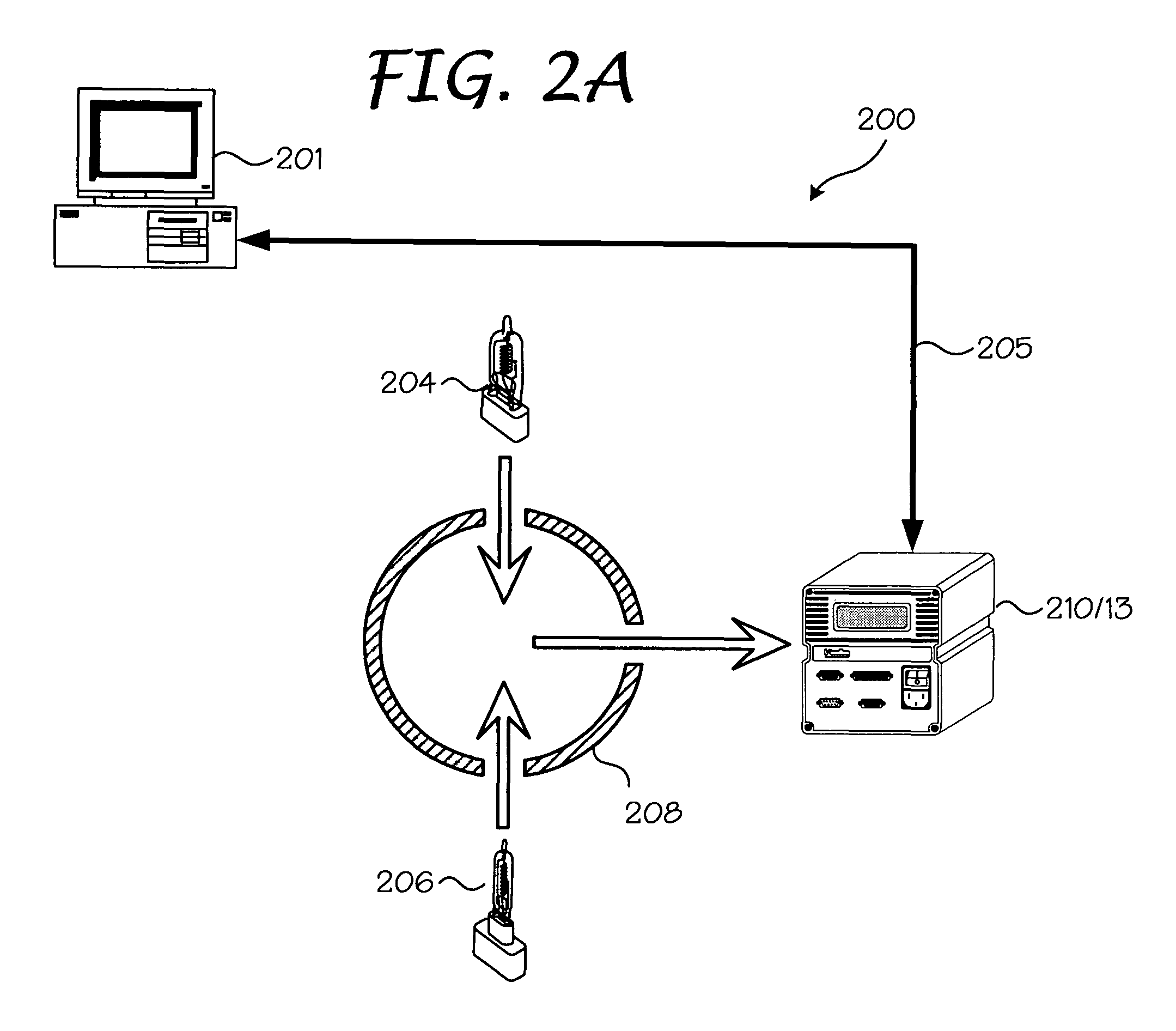
[0032]100: Prior Art Calibration System[0033]102: Production Spectrograph[0034]103: Detector[0035]104: Production Light Source[0036]200: Spectrograph Calibration System[0037]201: Spectrograph Calibration Module[0038]202: Production Spectrograph(s)[0039]203: Optical Detector Production Reference Light[0040]204: Source[0041]205: Calibrated Spectrograph Output Local Primary Standard[0042]206: Calibration Light Source Uncalibrated Spectrograph[0043]207: Output[0044]208: Integrating Sphere[0045]210: Reference Spectrograph[0046]213: Optical Detector[0047]300: Spectrograph Calibration System[0048]301: Spectrograph Calibration Module[0049]302: Production Spectrograph[0050]303: Optical Detector Production Reference Light[0051]304: Source[0052]305: Calibrated Spectrograph Output Local Primary Standard[0053]306: Calibration Light Source Uncalibrated Spectrograph[0054]307: Output[0055]308: Integrating Sphere[0056]310: Reference Spectrograph[0057]313: Optical...


PUM


Abstract

The present invention is directed to a system and method for radiometric calibration of spectroscopy equipment utilized in fault detection and process monitoring. Initially, a reference spectrograph is calibrated to a local primary standard (a calibrated light source with known spectral intensities and traceable to a reference standard). Other spectrographs are then calibrated from the reference spectrograph rather than the local primary calibration standard. This is accomplished by viewing a light source with both the reference spectrograph and the spectrograph to be calibrated. The output from the spectrograph to be calibrated is compared to the output of the reference spectrograph and then adjusted to match that output. The present calibration process can be performed in two stages, the first with the spectrographs calibrated to the reference spectrograph and then are fine tuned to a narrow band light source at the plasma chamber. Alternatively, the reference spectrograph can be calibrated to the local primary standard while optically coupled to the plasma chamber. There, the local primary standard calibration light source is temporarily positioned within the plasma chamber, or in a light chamber disposed along the interior of the chamber for calibrating the reference spectrograph. Other spectrographs can be calibrated to the reference spectrograph while coupled to the plasma chamber with the local primary standard calibration light source, thereby calibrating every component in the entire optical path to the reference spectrograph.

Description

CROSS-REFERENCE TO RELATED APPLICATION[0001]This application is related to and claims the benefit of co-pending U.S. Provisional Application Ser. No. 60 / 928,377, filed on May 7, 2007 and entitled “Calibration of a Radiometric Optical Monitoring System Used for Fault Detection and Process Monitoring,” and co-pending U.S. Provisional Application Ser. No. 61 / 045,585, filed on Apr. 16, 2008 and entitled “Calibration of a Radiometric Optical Monitoring System Used for Fault Detection and Process Monitoring,” which are assigned to the assignee of the present invention. The above identified applications are incorporated by reference herein in their entireties.BACKGROUND OF THE INVENTION[0002]The present invention relates generally to obtaining accurate optical emission spectroscopy measurements. More particularly, the present invention relates to a system and method for radiometric calibration of spectroscopy equipment utilized in fault detection and process monitoring.[0003]In the art of ...

Claims


Application Information

Patent Timeline
Patent Type & Authority Patents(United States)
IPC IPC(8): G01J3/00
CPCG01J3/28G01J3/443G01J2003/2866G01J3/02
Inventor WHELAN, MIKEKUENY, ANDREW WEEKSHARVEY, KENNETH C.CORLESS, JOHN DOUGLAS
Owner VERITY INSTR
Why Eureka
Try Eureka