
Music detector for echo cancellation and noise reduction

a music detector and echo cancellation technology, applied in the field of telephones, can solve the problems of many sources of noise in the telephone system, the envelope of both types of signals is relatively constant, and the noise reduction circuitry to reduce background music, so as to avoid distorting the signal

Active Publication Date: 2012-02-28
CIRRUS LOGIC INC
View PDF22 Cites 15 Cited by
  • Summary
  • Abstract
  • Description
  • Claims
  • Application Information

AI Technical Summary

Benefits of technology

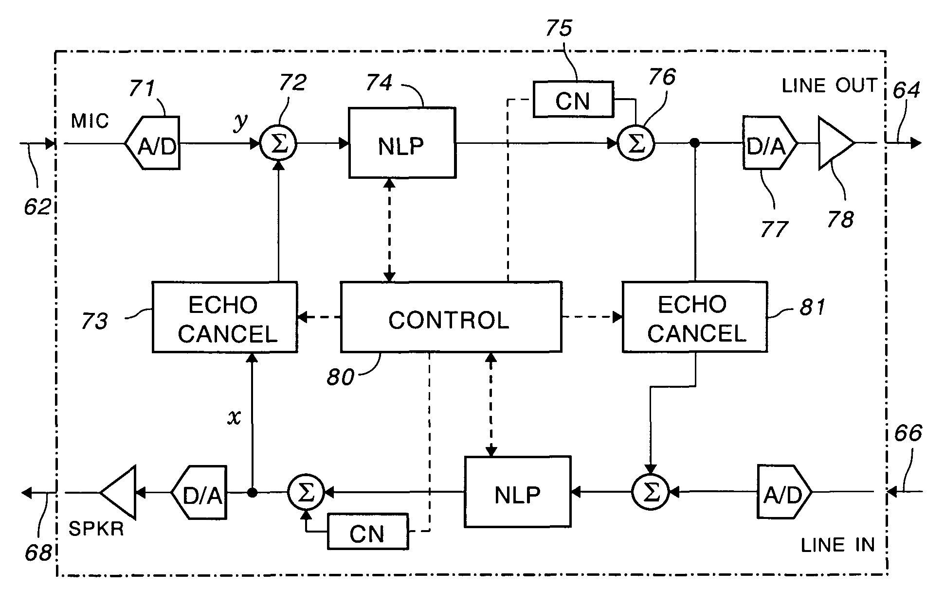
The patent describes a method for detecting music and distinguishing it from noise using spectral flatness. The method involves dividing the audio signal into smaller parts and measuring the flatness of each part. These measures are then combined and compared with a threshold to determine if there is music or noise. If music is detected, the noise reduction circuitry is turned off to avoid distorting the signal, and the residual echo suppression circuitry is also turned off to avoid inserting comfort noise. The technical effect of this invention is to improve the accuracy and quality of music detection and noise reduction in audio signals.

Problems solved by technology

There are many sources of noise in a telephone system.
One of the main challenges in distinguishing music from noise is that the envelopes of both types of signal are relatively constant.
Most known voice activity detectors measure the energy content of the envelope, which means that a voice activity detector will detect music as noise and will cause the noise reduction circuitry to reduce the background music, distorting the signal.
It will also cause the non-linear processor to suppress the residual echo, which will then insert the comfort noise after suppressing the residual echo.
This insertion of comfort noise can annoy a listener because the music will become intermittent.
Noise and non-speech are problems, as is picking the correct time interval.
Many of these methods are not robust enough to distinguish different genre of music unambiguously from noise.
Some of the methods are not meant to be done in real time because of large computational requirements; e.g. requiring wide data bus, large amounts of storage, or long execution time for analysis.

Method used


Image

  • Music detector for echo cancellation and noise reduction
  • Music detector for echo cancellation and noise reduction
  • Music detector for echo cancellation and noise reduction

Examples


Embodiment Construction

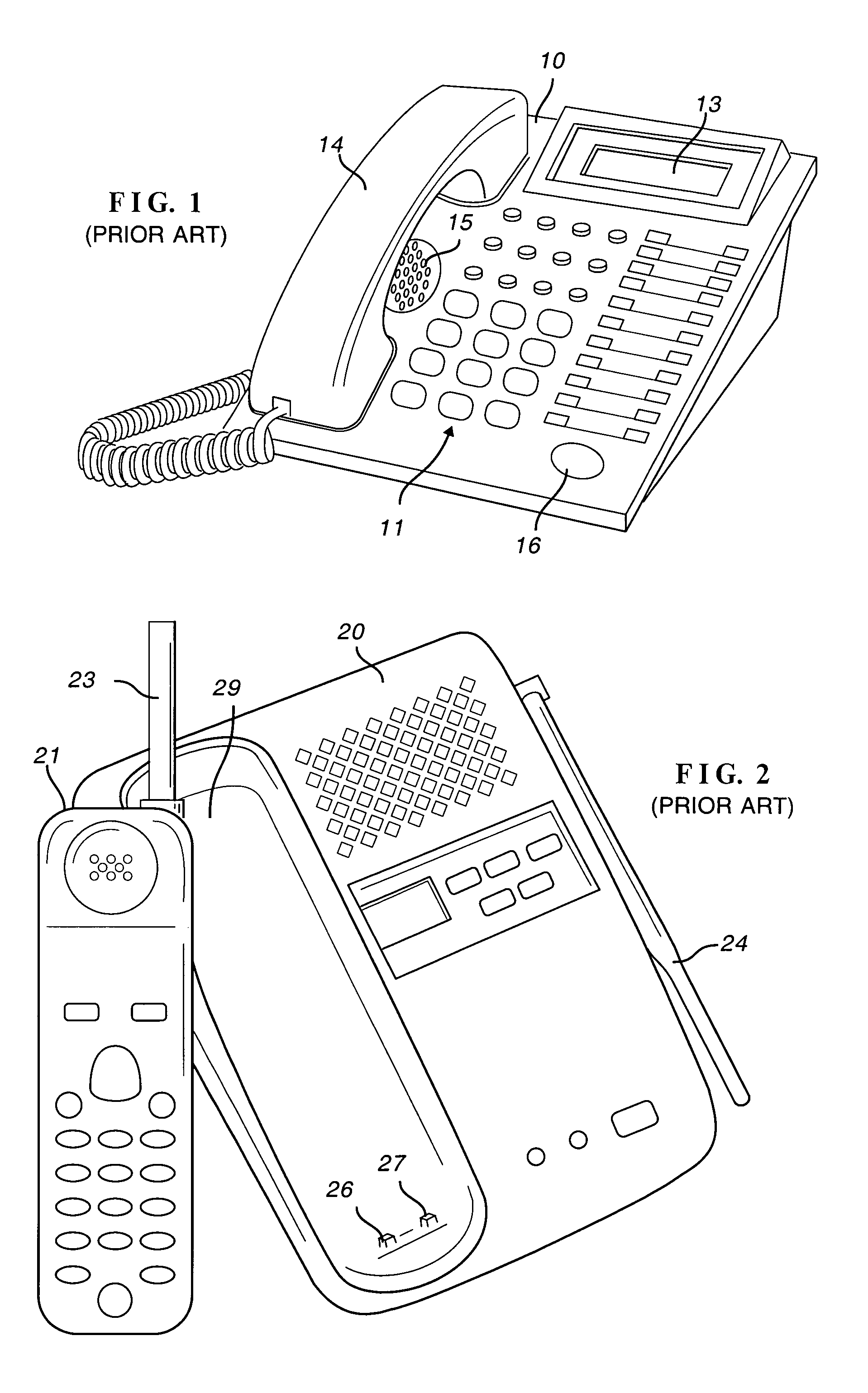
[0030]This invention finds use in many applications where the electronics is essentially the same but the external appearance of the device may vary. FIG. 1 illustrates a desk telephone including base 10, keypad 11, display 13 and handset 14. As illustrated in FIG. 1, the telephone has speakerphone capability including speaker 15 and microphone 16. The cordless telephone illustrated in FIG. 2 is similar except that base 20 and handset 21 are coupled by radio frequency signals, instead of a cord, through antennas 23 and 24. Power for handset 21 is supplied by internal batteries (not shown) charged through terminals 26 and 27 in base 20 when the handset rests in cradle 29.

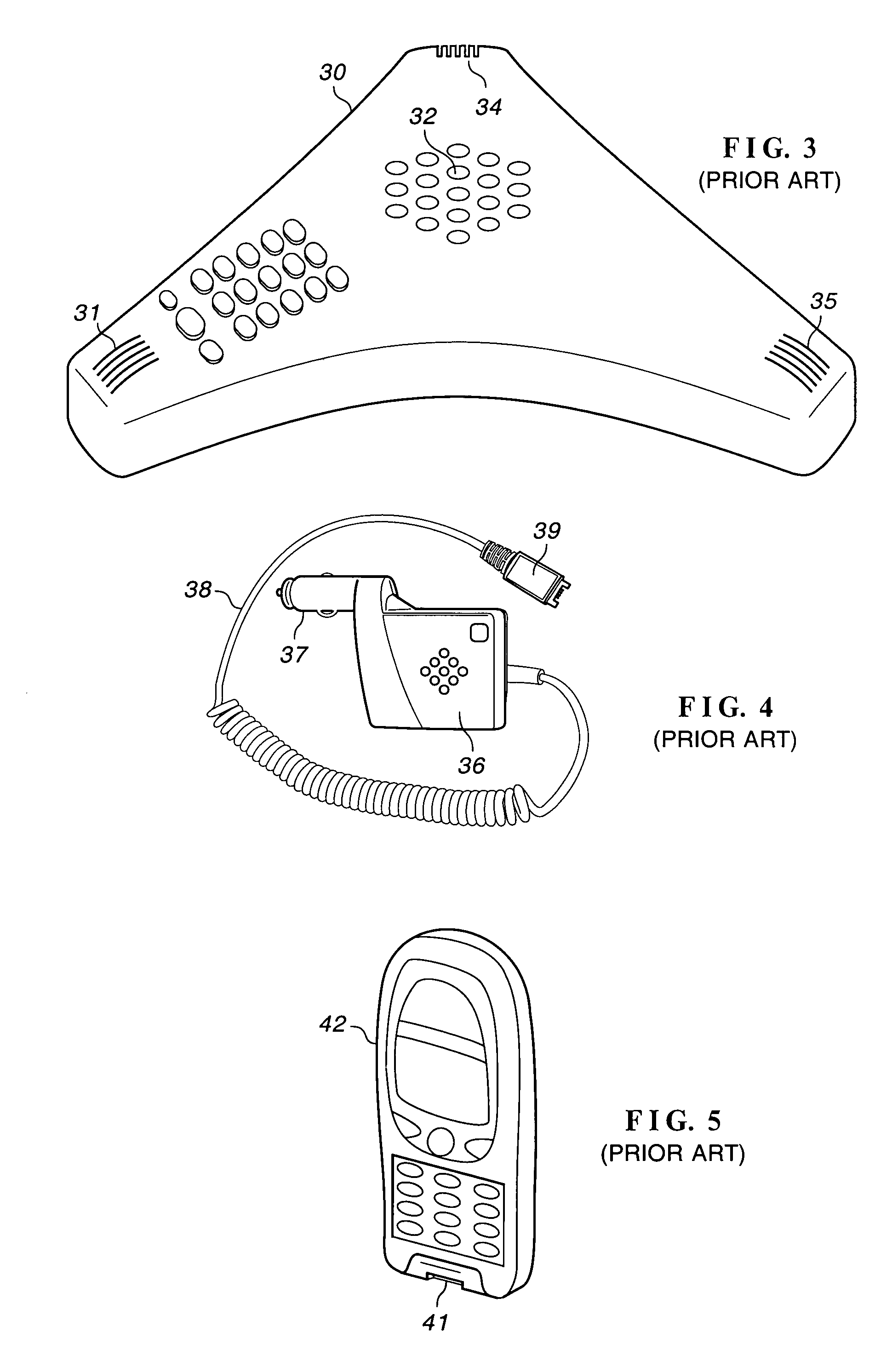
[0031]FIG. 3 illustrates a conference phone or speakerphone such as found in business offices. Telephone 30 includes microphone 31 and speaker 32 in a sculptured case. Telephone 30 may include several microphones, such as microphones 34 and 35 to improve voice reception or to provide several inputs for echo rejection...


PUM


Abstract

An audio signal is divided among exponentially related subband filters. The spectral flatness measure in each subband signal is determined and the measures are weighted and combined. The sum is compared with a threshold to determine the presence of music or noise. If music is detected, the noise estimation process in the noise reduction circuitry is turned off to avoid distorting the signal. If music is detected, residual echo suppression circuitry is also turned off to avoid inserting comfort noise.

Description

BACKGROUND OF THE INVENTION[0001]This invention relates to a telephone employing circuitry for echo cancellation and noise reduction and, in particular, to such circuitry that includes a music detector.[0002]As used herein, “telephone” is a generic term for a communication device that utilizes, directly or indirectly, a dial tone from a licensed service provider. As such, “telephone” includes desk telephones (see FIG. 1), cordless telephones (see FIG. 2), speakerphones (see FIG. 3), hands-free kits (see FIG. 4), and cellular telephones (see FIG. 5), among others. For the sake of simplicity, the invention is described in the context of telephones but has broader utility; e.g. communication devices that do not utilize a dial tone, such as radio frequency transceivers. Although described in the context of telephones, the invention has broader application in the analysis of audio signals.[0003]While not universally followed, the prior art generally associates noise “suppression” with su...

Claims


Application Information

Patent Timeline
Patent Type & Authority Patents(United States)
IPC IPC(8): G10L11/06G10L25/93
CPCG10H1/0058G10L25/90G10H2210/046G10H2210/281G10H2240/241G10H2240/251G10H2250/031G10L19/0204G10L21/02
Inventor EBENEZER, SAMUEL PONVARMA
Owner CIRRUS LOGIC INC
Learn More