Safety system for firearms

a safety system and firearm technology, applied in the field of firearm safety systems, can solve the problems of not being able to prevent the authorised user from accidentally or intentionally firing the weapon, and achieve the effect of restricting the usability of the firearm

Active Publication Date: 2012-03-06
BARNES KEVIN TROY
View PDF16 Cites 32 Cited by
  • Summary
  • Abstract
  • Description
  • Claims
  • Application Information

AI Technical Summary

Benefits of technology

[0011]The system of the present invention prevents the use or misuse of a firearm equipped with the safety device within a designated area in which the use of firearms is prohibited, e.g. police stations, schools etc. To enable this, the base unit is disposed within the designated area whereby as soon as a firearm equipped with the safety device is brought into the designated area the locking mechanism is actuated thereby locking the firing mechanism of the firearm. Conversely, as soon the firearm is taken outside the designated area, that is, outside the predetermined distance range, the base unit and the safety device stop exchanging and processing the command signal and the actuating circuit is prompted by the transmitter and / or receiver of the safety device to release the locking mechanism.
[0016]Once the safety device and the tag device are separated by a distance greater than the predetermined distance, the reader device prompts the actuating circuit to actuate the locking mechanism thereby causing the locking mechanism to assume a locking mode capable of preventing a firearm equipped with the safety device from firing. Ideally, the predetermined distance range is between 0 m and 1 m. The above-described feature of the system of the invention further restricts the usability of a firearm when the authorised user is outside the predetermined distance of operability of the command signal of the transmitter and / or receiver of the base unit so that the firearm can be only used by an authorised user, i.e. a wearer of the tag device and within an area in the immediate vicinity of an authorised user wearing the tag device.
[0023]In one preferred arrangement, the locking mechanism is arranged to remain in the locking mode at all times without the need for the actuating circuit to keep it in the locked mode. Ideally, the actuating circuit is only needed to switch the locking mechanism between the locked and the released modes, thereby minimising the power required for manipulating the locking mechanism. In one preferred arrangement, the actuating circuit comprises an electro-mechanical element, such as, for example, a solenoid or an electromagnetic actuator for actuating the locking mechanism. Preferably, once the locking mechanism is in the locked mode, it can only be released by the actuating circuit. In one arrangement, the locking mechanism comprises a pin or a catch member moveable under the influence of the actuating circuit in and out of locking engagement with the firing mechanism of the firearm.

Problems solved by technology

The known device, however, cannot prevent the authorised user from accidentally or intentionally firing the weapon in a place or circumstance where firing is prohibited altogether.

Method used


Image

  • Safety system for firearms
  • Safety system for firearms
  • Safety system for firearms

Examples


Embodiment Construction

[0025]The invention will now be described with reference to the accompanying drawings which show by way of example only a firearm enabling and disabling electronic system according to the invention. In the drawings:

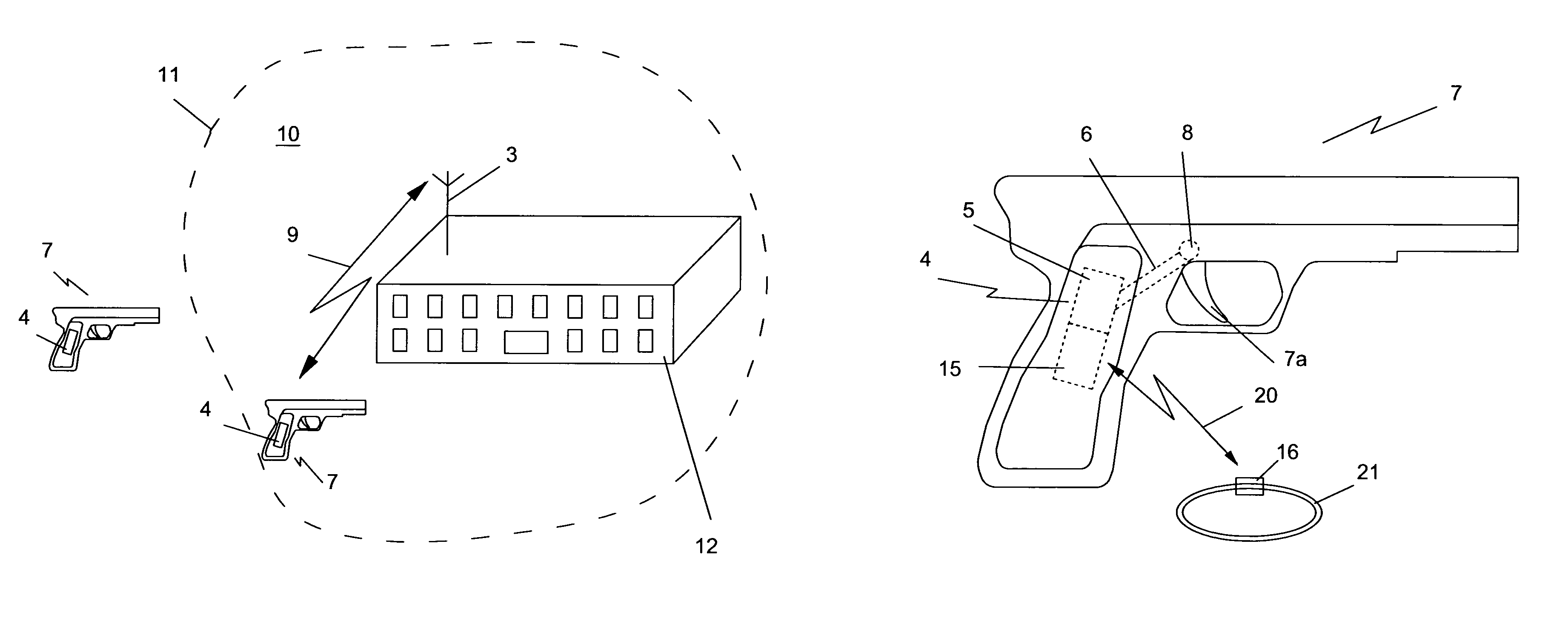
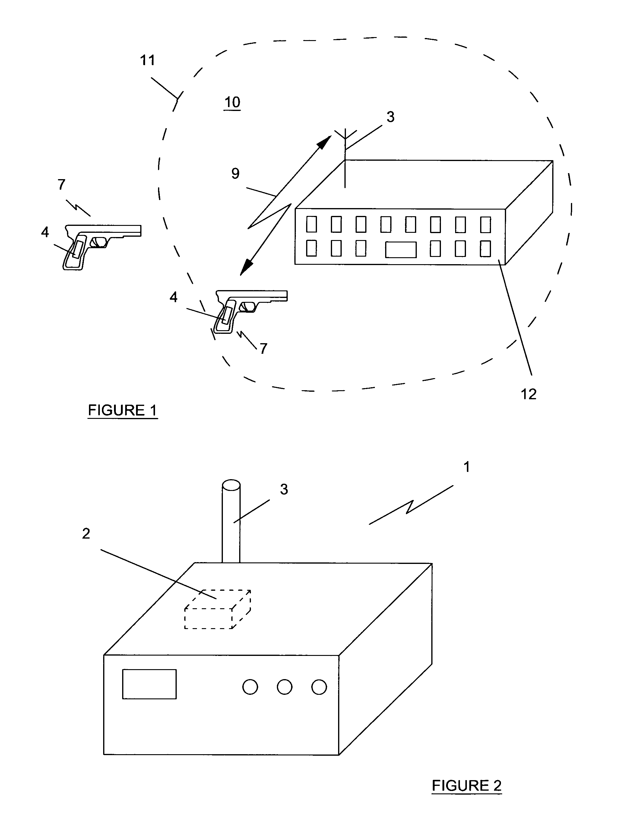
[0026]FIG. 1 is a schematic illustration of a system according to the invention;

[0027]FIG. 2 is a perspective schematic view of a base unit of the system of the invention;

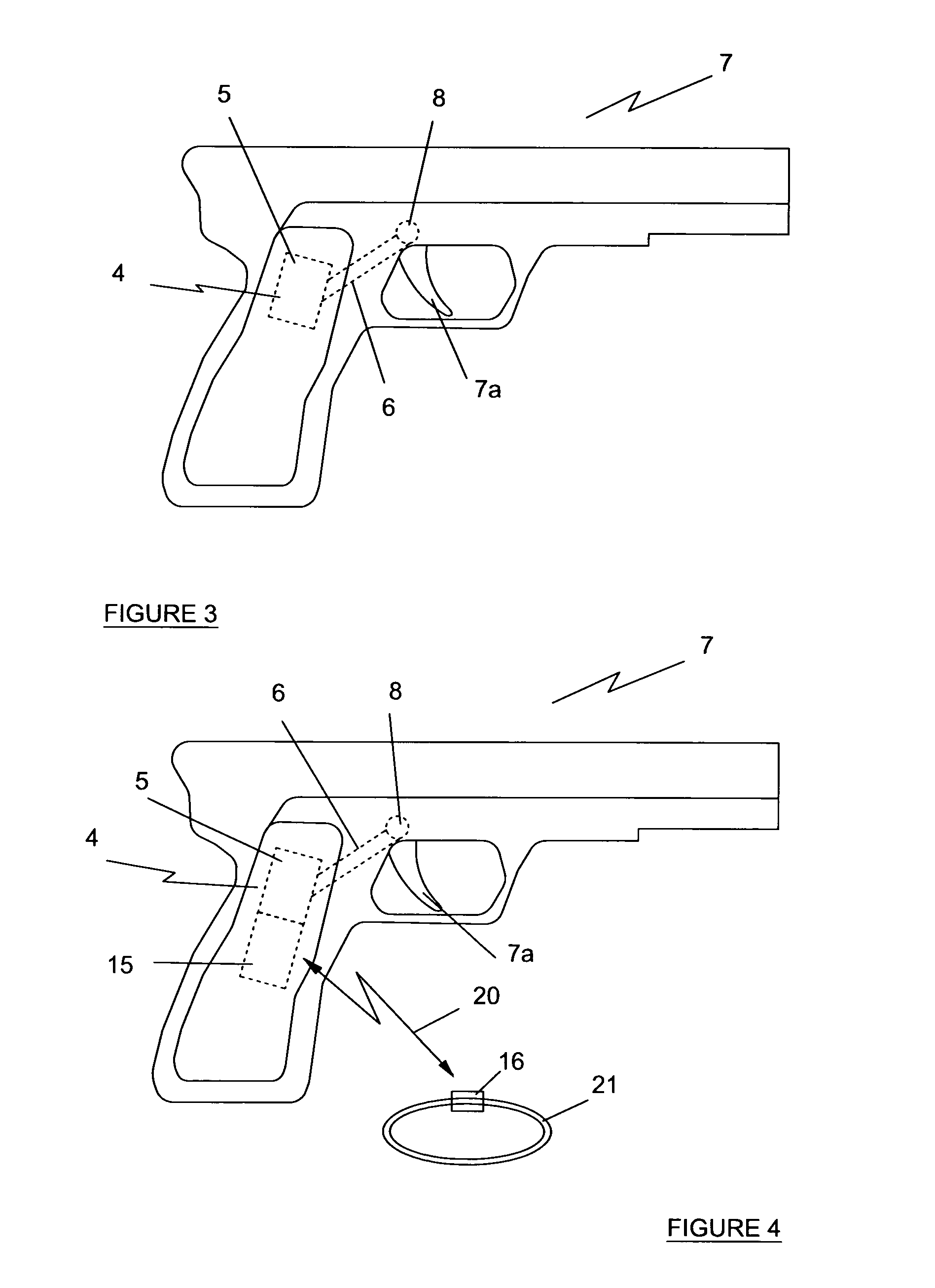
[0028]FIG. 3 is a schematic view of a firearm equipped with a safety device according to the invention; and

[0029]FIG. 4 is a schematic illustration of a further safety feature of the system of the invention.

[0030]Referring to FIGS. 1 to 3, a firearm enabling and disabling electronic system of the present comprises at least one base unit 1 comprising a transmitter and / or receiver 2 and an antenna 3.

[0031]The base unit 1 co-operates with a safety device generally indicated by reference numeral 4 in FIG. 3. The safety device 4 is shown built-into a firearm 7 and includes a transmitter and / or receiver 5 adap...


PUM


Abstract

A firearm enabling and disabling electronic system comprising a base unit (1) and a safety device (4) adapted to be incorporated into a firearm (7). Each of the base unit (1) and the safety device (4) has a transmitter and / or receiver (2, 5) adapted to exchange and process wireless command signals with each other. The safety device (4) has an actuating circuit (6) which is controlled by the transmitter and / or receiver (5) of the safety device (4) and is adapted to actuate a locking mechanism (8), wherein in the locking mechanism is operable to prevent a firearm from firing. The wireless command signal (9) is operable within a predetermined distance between the base unit (1) and the safety device (4) so that when the safety device (4) is located within the predetermined distance from the base unit (1), transmitters and / or receivers (2, 5) exchange the wireless command signal which causes the transmitter and / or receiver (5) of the safety device (4) to prompt the actuating circuit (6) to actuate the locking mechanism (8) thereby causing the locking mechanism (8) to assume a locking mode in which a firearm (7) is prevented from firing.

Description

FIELD OF THE INVENTION[0001]The present invention relates to a safety system for a firearm and in particular to an electronic system for enabling / disabling a firearm.BACKGROUND OF THE INVENTION[0002]Firearms equipped with electronic activation / de-activation devices are known. EP0912871 B1 describes a firearm which has a safety feature which includes an electronically controlled locking mechanism which blocks the firing mechanism of the firearm. The locking mechanism is coupled with a transmitter / receiver unit provided on the firearm. A second transmitter / receiver unit is provided to an authorised user. The transmitter / receiver unit of the firearm wirelessly exchanges coded signals with the authorised user's device so that when the firearm is within a pre-determined distance range from the authorised user and the identification codes of the devices match, the locking mechanism is released. Such a system is useful to prevent the use or misuse of the firearm by any person other than th...

Claims


Application Information

Patent Timeline
Patent Type & Authority Patents(United States)
IPC IPC(8): F41A17/06
CPCF41A17/063
Inventor O'SHAUGHNESSY, PATRICKMCNAMARA
Owner BARNES KEVIN TROY
Why Eureka
Try Eureka