Method and apparatus for machining parts of partial revolution

a technology of partial revolution and machining method, which is applied in the direction of grinding drive, grinding machine components, manufacturing tools, etc., can solve the problems of presenting challenges in the control of the dimension of the part produced, and achieve the effect of preventing slippag

Inactive Publication Date: 2012-03-06
C M GRINDING
View PDF8 Cites 1 Cited by
  • Summary
  • Abstract
  • Description
  • Claims
  • Application Information

AI Technical Summary

Problems solved by technology

However, not all parts are symmetrical, yet need to have a portion of their perimeter machined as revolved about an axis while the remainder of the part is a shape that could not be manufactured through simply revolving the part to remove material.
Machining only a portion of the perimeter where it is desired that the perimeter be concentric with an axis of the part would be useful, but would present challenges with regard to controlling dimensions of the part produced.

Method used


Image

  • Method and apparatus for machining parts of partial revolution
  • Method and apparatus for machining parts of partial revolution
  • Method and apparatus for machining parts of partial revolution

Examples


Embodiment Construction

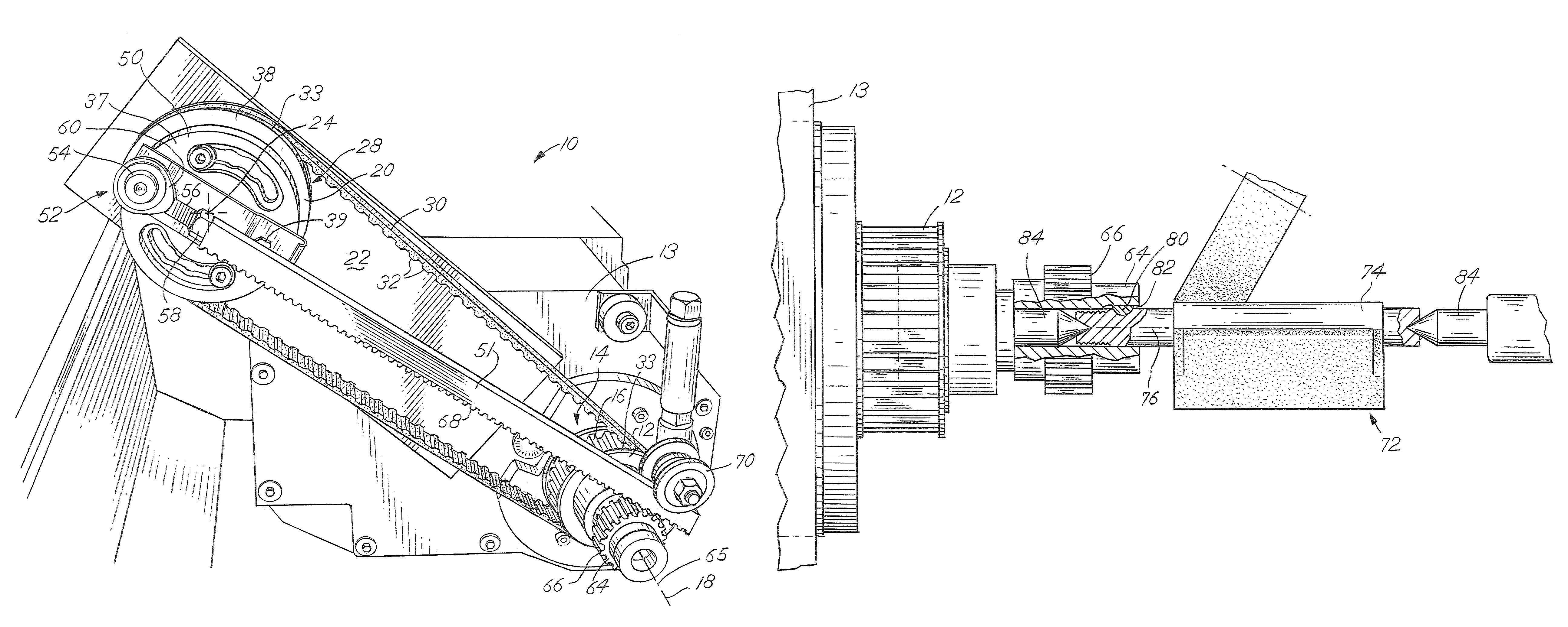
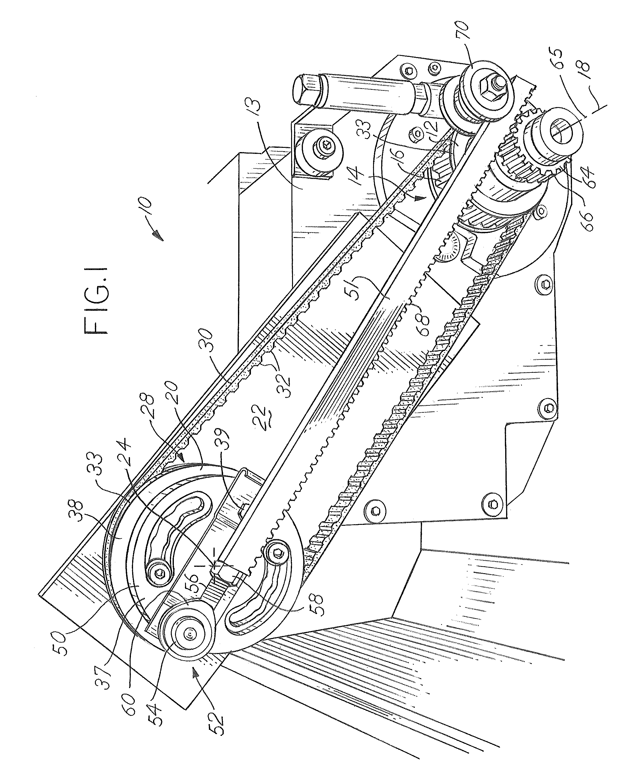
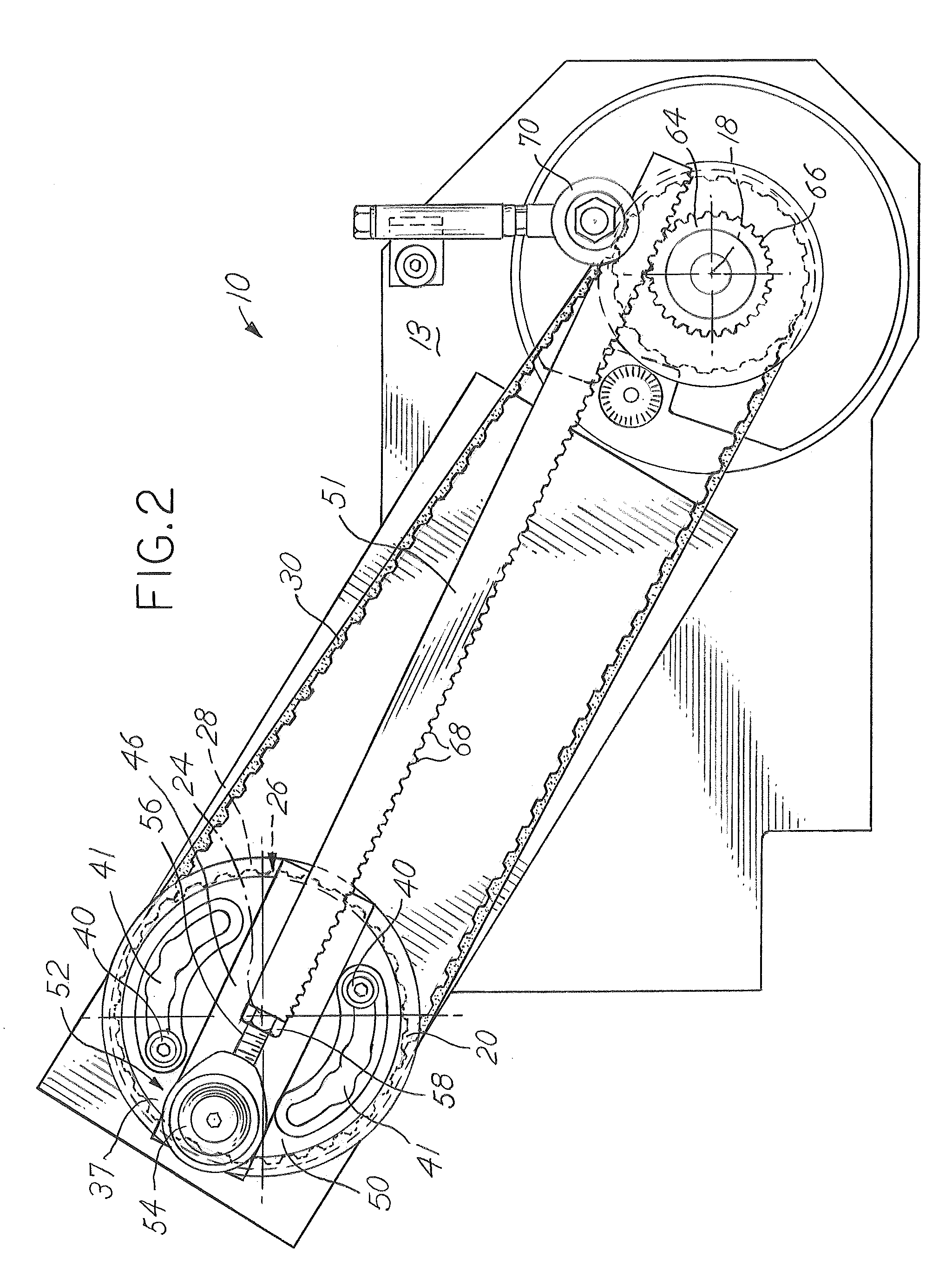
[0012]The machine 10 of this invention is shown in FIG. 1 and is a modified version of a typical grinding machine. The motor of the machine 10 rotates a driving sheave 12 that extends from the face 13 of the machine 10. The driving sheave 12 has an outer surface 14 with teeth 16. The driving sheave 12 rotates about a first axis 18, which corresponds to its centerline.

[0013]A first driven sheave 20 is mounted to a mounting plate 22 that extends from the face 13 of the machine 10. The first driven sheave 20 rotates about a second axis 24 that is fixed with respect to the first axis 18 of the driving sheave 12. The first driven sheave 20 also has teeth 26 around its outer surface 28. A belt 30 is wrapped around a portion of each of the outer surfaces 14, 28 of the driving sheave 12 and the first driven sheave 20 so that when the driving sheave 12 rotates, the first driven sheave 20 also rotates. The belt 30 has teeth 32 that engage with the teeth 16, 26 on the driving sheave 12 and the...


PUM

PropertyMeasurementUnit
distanceaaaaaaaaaa
flexibleaaaaaaaaaa
rotationaaaaaaaaaa

Abstract

A machine and method for machining parts of partial revolution. The machine has a driving sheave rotatable about a first axis and a first driven sheave rotatable about a second axis fixed relative to the first axis. An eccentric link is rotatably connected to the first driven sheave at a pivotal connection that is spaced a predetermined distance from the second axis. A belt is wrapped around the driving sheave and the first driven sheave so that rotation of the driving sheave causes the first driven sheave to rotate. A second driven sheave is rotatable about a third axis fixed relative to the second axis. A second driven sheave contacts with the eccentric link. The eccentric link moves in a reciprocating motion when said first driven sheave is caused to rotate and causes reciprocating rotary motion in the second driven sheave, which is transferred to a part being machined.

Description

BACKGROUND OF THE INVENTION[0001]Machining parts of revolution is a well established operation that is usually accomplished using a rotating machine such as a lathe or a grinding machine. Doing so will result in a part having a symmetrical cross section when sectioned about the axis of rotation. However, not all parts are symmetrical, yet need to have a portion of their perimeter machined as revolved about an axis while the remainder of the part is a shape that could not be manufactured through simply revolving the part to remove material.[0002]Machining only a portion of the perimeter where it is desired that the perimeter be concentric with an axis of the part would be useful, but would present challenges with regard to controlling dimensions of the part produced. A machine to perform that task would ideally provide for adjustment of the angular portion of the perimeter that would be machined concentric to the axis of rotation. When holding the part it would be useful to provide t...

Claims


Application Information

Patent Timeline
Patent Type & Authority Patents(United States)
IPC IPC(8): B23C9/00B23C5/16
CPCB24B5/04B24B47/16Y10T82/26Y10T82/10
Inventor MAYFIELD, CALVIS L.
Owner C M GRINDING
Why Eureka
Try Eureka