
Tube loading assembly for peristaltic pump

a technology of peristaltic pumps and loading assemblies, which is applied in the direction of flexible member pumps, machines/engines, positive displacement liquid engines, etc., can solve the problems of difficult production and use, difficult to make and use, and compromised structural simplicity, etc., to achieve easy operation, simple mechanical design, and avoid finger pinching

Active Publication Date: 2012-03-06
MOU DUEN GANG
View PDF7 Cites 19 Cited by
  • Summary
  • Abstract
  • Description
  • Claims
  • Application Information

AI Technical Summary

Benefits of technology

[0009]In summary, the present invention simplifies the mechanical design for tube loading and provides easy operation at the same time. When unloading, the tube pressing member swings wide open and exposes the pumping head for tube mounting and demounting without risk of finger pinching. This releasable and retractable tube pressing member simply swings back to a locked position for pump action and fluid flow.
[0010]A spring mounted tube pressing member is employed to simplify the make and use of a peristaltic pump. It loads and unloads an elastic tubing piece between a continuously circulating tube occluding rollers and a tube pressing member by selectively installing the spring and the accompanying tube pressing member in a locked loading position for fluid transfer, and in an open unloading position from the circulating tube occluding roller assembly for unhindered mounting and demounting of an elastic tube section as well as easy gravity or air back-pressure flushing of the system. Preferably, a pivotally mounted two-arm helical torsion spring meets the above need with a retractable tube pressing member mounted on one arm, and a pressuring device, which adjusts pressure on the tube pressing member, on the other arm.
[0011]Further benefit of the invention is the dynamic and decreasing pressure distribution on the tube pressing member in the direction of the fluid flow. This decreasing dynamic pressure not only aids the flex life of the tube section but also enables the occluded fluid to move through the tube in one direction while minimizing undue fluid back pressure in the opposite direction.
[0012]Additional objective in easy tube mounting and demounting is to provide quick and straightforward replacement of either stand-alone disposable tube cassette, or a disposable tube section attached to the tube pressing member.

Problems solved by technology

Its benefit in structural simplicity is compromised because both hands are needed at the same time.
Besides tube loading, tube caring and dynamic compression mechanisms tend to be mechanically complex, they are also difficult to make and use.

Method used


Image

  • Tube loading assembly for peristaltic pump
  • Tube loading assembly for peristaltic pump
  • Tube loading assembly for peristaltic pump

Examples


Embodiment Construction

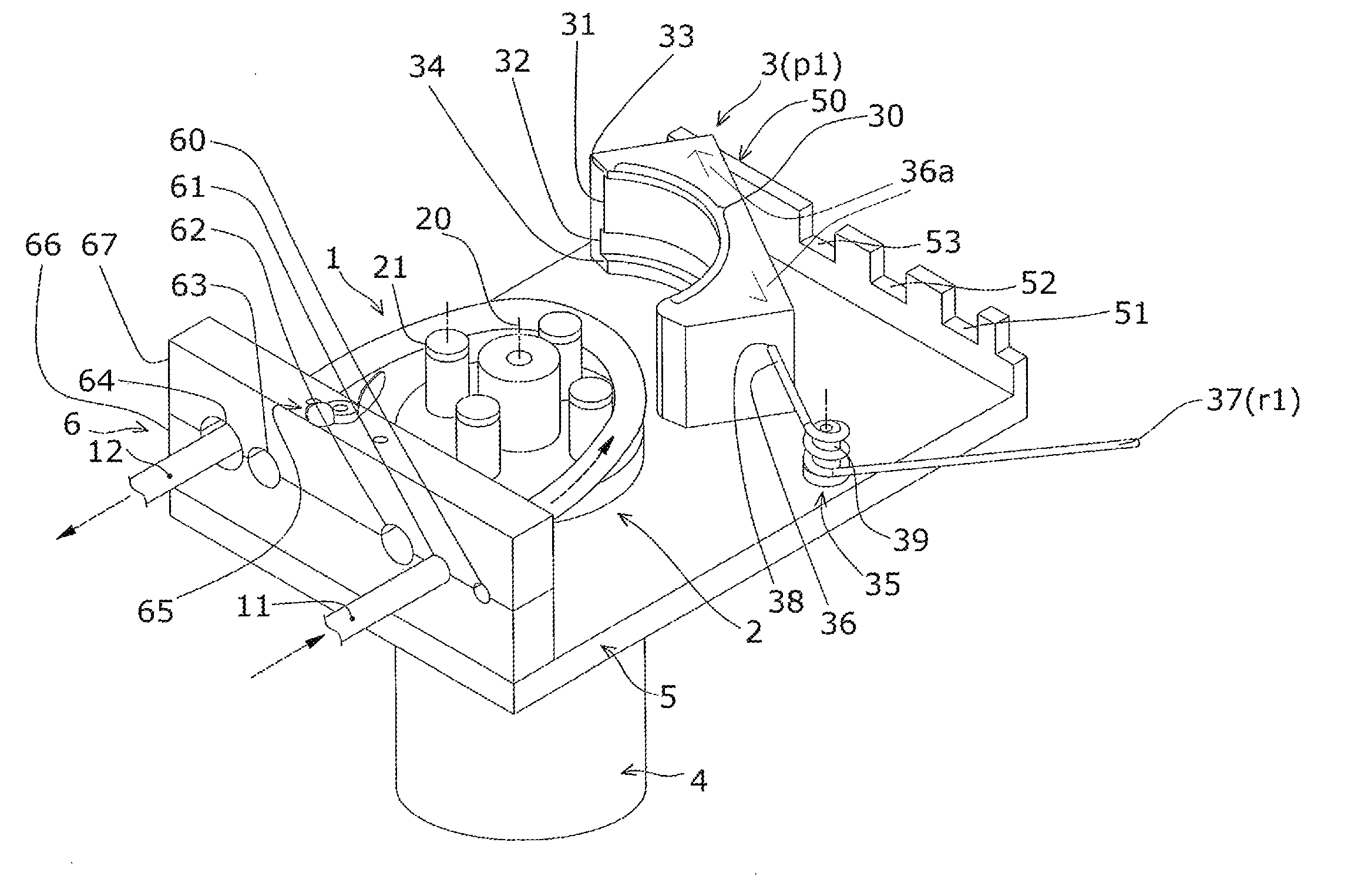
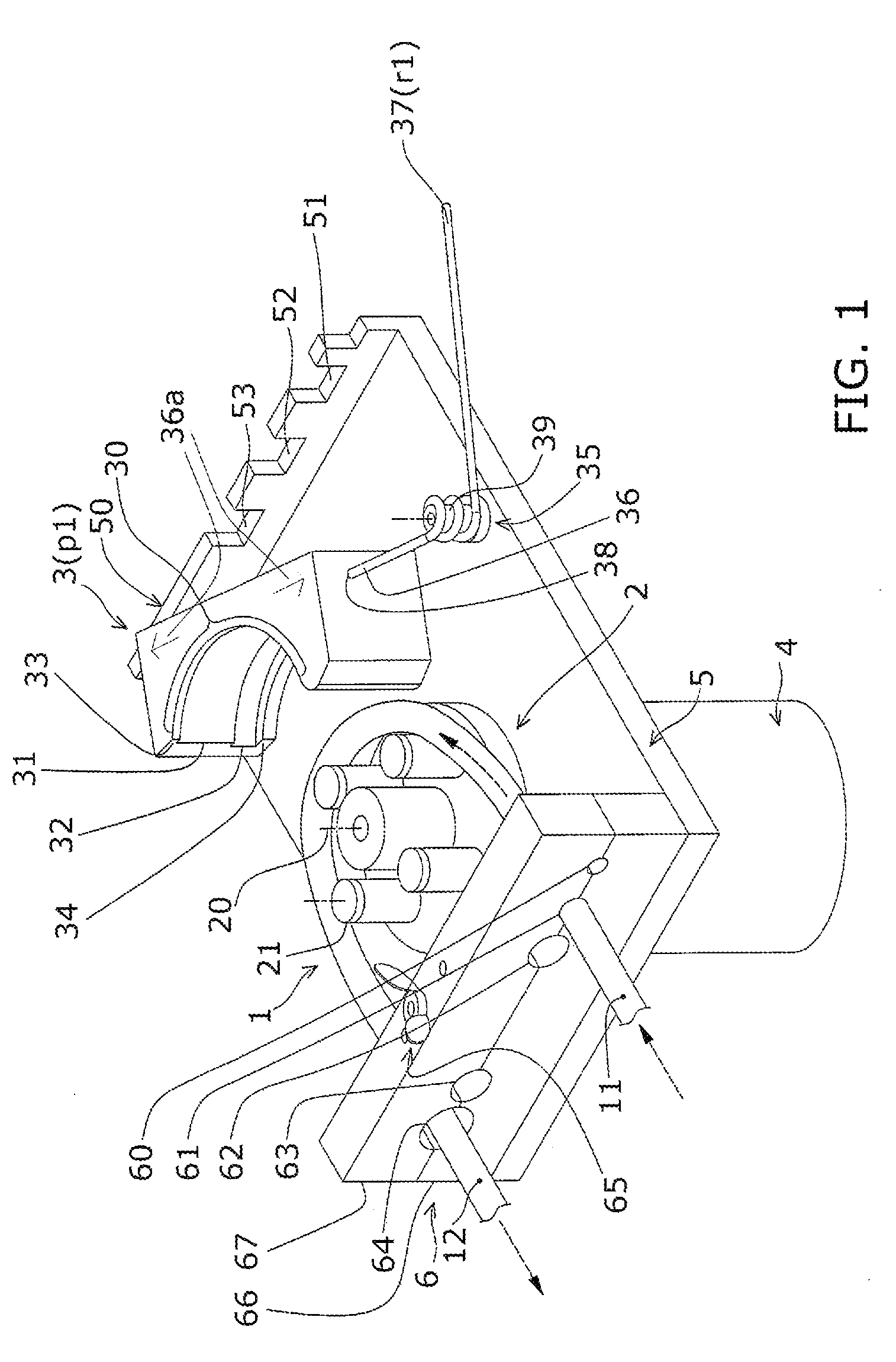
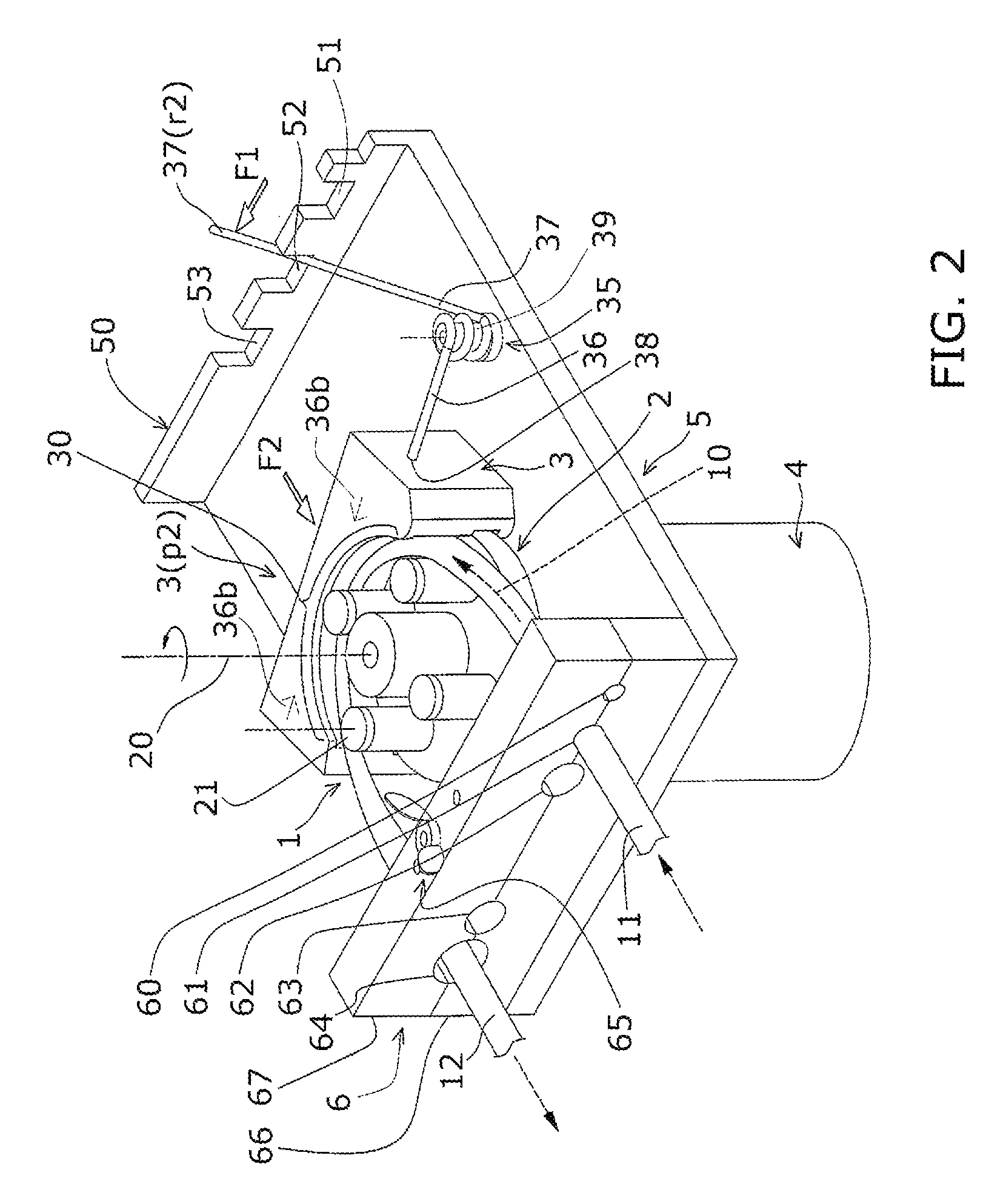
[0018]As shown in FIGS. 1 and 2, a peristaltic pump assembly in accordance with the present invention includes a base plate 5, a motor 4, a rotor assembly 2 with a plurality of circulating rollers 21, and a tube pressing member 3 with an arcuate side 30 forming a tube track 31. In such arrangement, the space between the rollers 21 on the rotor assembly 2 and the pressing member 3 is less than the diameter of the tube 1 and the tube 1 must be squeezed in between. The pump assembly of the present invention in an open (or unlocked) position with a tube section in place is shown in FIG. 1. An elastic tube section 1 is installed between a plurality of freely rotating rollers 21 installed on a rotor assembly 2 circulating about an axis 20 and a tube track 31 formed on a tube pressing member 3. The tube pressing member 3 is pressed and locked in the proximity of the circular orbit of the rollers 21 by force from a two-arm helical torsion spring 35 pivotally mounted on a bolt 39 fixed to th...


PUM


Abstract

A spring mounted tube pressing member for peristaltic pumps allows loading and unloading of an elastic tube section between the tube pressing member and a continuously revolving rotor assembly by selectively moving between a locked position for fluid transfer and an open position for unhindered mounting and demounting of the tube section or a replaceable tube cassette. Not only is the pressure on the tube pressing member adjustable by the spring used, its dynamic pressure distribution on the tube section also prolongs the tube flex life and reduces fluid back mixing and pulsation in the tube.

Description

BACKGROUND OF THE INVENTION[0001]1. Field of the Invention[0002]The present invention relates generally to the field of peristaltic pumps. More particularly, the present invention relates to a tube loading assembly comprising a tube pressing member riding on one arm of a two-arm torsion spring.[0003]2. Description of the Related Art[0004]A peristaltic pump moves and meters liquid through tubing of a dispensing circuit free of ambient contaminants. The dispensing circuit is releasably mounted to the pump and the tubing of the dispensing circuit is loaded in the pump. The rotating pump drives liquids through the tubing of the dispensing circuit. In a hospital or lab setting, the liquid transferred are body fluids, intravenous solutions, extracorporeal bloods, reagent solutions, nutrient culture media, etc.[0005]A peristaltic pump assembly usually includes a base, a motor, a rotor assembly with circulating tube occluding rollers, and a tube pressing member with a tube track or raceway....

Claims


Application Information

Patent Timeline
Patent Type & Authority Patents(United States)
IPC IPC(8): F04B43/08F04B45/06
CPCF04B43/1284
Inventor MOU, DUEN-GANG
Owner MOU DUEN GANG
Learn More