Light emitting device for AC operation

a light emitting device and ac operation technology, applied in the direction of semiconductor devices for light sources, lighting and heating apparatus, electroluminescent light sources, etc., can solve the problems of easy reverse current breakage, inability to operate the device continuously, and easy failure of the chip, so as to reduce the number of light emitting cells and wires formed on a single substrate , the effect of reducing the failure rate of the chip in the manufacturing process and reducing manufacturing costs

Inactive Publication Date: 2012-03-06
SEOUL VIOSYS CO LTD
View PDF12 Cites 15 Cited by
  • Summary
  • Abstract
  • Description
  • Claims
  • Application Information

AI Technical Summary

Benefits of technology

[0011]An object of the present invention is to provide an AC light emitting device, which can appropriately reduce the number of light emitting cells and wires formed on a single substrate.
[0012]Another object of the present invention is to provide an AC light emitting device capable of simplifying patterning and wire connecting processes of light emitting cells formed on a single substrate.
[0013]A further object of the present invention is to provide an AC light emitting device capable of preventing overvoltage from being applied to light emitting cells in an array to which reverse voltage is applied by an AC power source.
[0014]According to one aspect of the present invention for achieving the objects, an AC light emitting device includes at least four substrates. Serial arrays each of which has a plurality of light emitting cells connected in series are positioned on the substrates, respectively. Meanwhile, first connector means electrically connect the serial arrays formed on respective different substrates. At least two array groups each of which has at least two of the serial arrays connected in series by the first connector means are formed. The at least two array groups are connected in reverse parallel to operate. Accordingly, it is possible to provide an AC light emitting device capable of reducing the number of light emitting cells formed on a single substrate. Further, since all the light emitting cells formed on the single substrate can be connected in series, the patterning and wire forming processes of the light emitting cells can be simplified.
[0015]Meanwhile, at least one second connector means may electrically connect the first connector means corresponding to each other provided in the array groups connected in reverse parallel. The second connector means prevent overvoltage from being applied to a specific array in the array group to which reverse voltage is applied during operation. Accordingly, it is possible to protect the light emitting cells in the array group to which a reverse voltage is applied.
[0021]According to embodiments of the present invention, a plurality of single chips having an serial array of light emitting cells are used, whereby the number of the light emitting cells and wires formed on a single substrate can be appropriately reduced. Accordingly, a chip failure rate in a manufacturing process can be decreased, thereby reducing manufacturing costs. Further, since it is not required to connect light emitting cells formed on a single substrate in reverse parallel, the patterning and wire connecting process of the light emitting cells formed on the single substrate can be simplified. Furthermore, second connector means for connecting array groups to one another are employed, thereby providing an AC light emitting device capable of preventing overvoltage from being applied to light emitting cells in an array to which a reverse voltage is applied. In addition, since a plurality of single chips are used, the single chips for emitting lights with different light emitting wavelengths can be disposed, thereby providing an AC light emitting device for emitting lights with various wavelengths.

Problems solved by technology

As a result, there are problems in that the LED does not continuously emit light and is easily broken by reverse current.
However, in the single chip light emitting device, a failure of any one of the light emitting cells connected in series or disconnection / short circuit of wires results in a chip failure that makes the AC operation of the device impossible.
In particular, in a cast that the single chip includes a few tens of light emitting cells and wires for connecting them in series and reverse parallel so as to be driven under a high voltage, e.g., a 110 / 220V AC power source used for general household, a chip failure may be easily occurred due to a large number of the light emitting cells and the wires formed on the single chip.
Further, as a plurality of light emitting cells are connected in series and reverse parallel on the same substrate, it is likely that short circuits between wires for connecting the light emitting cells increase, and the processes of patterning the light emitting cells are complicated.

Method used


Image

  • Light emitting device for AC operation
  • Light emitting device for AC operation
  • Light emitting device for AC operation

Examples


Embodiment Construction

[0028]Hereinafter, preferred embodiments of the present invention will be described in detail with reference to the accompanying drawings. The following embodiments are provided only for illustrative purposes so that those skilled in the art can fully understand the spirit of the present invention. Therefore, the present invention is not limited to the following embodiments but may be implemented in other forms. In the drawings, the widths, lengths, thicknesses and the like of elements may be exaggerated for convenience of illustration. Like reference numerals indicate like elements throughout the specification and drawings.

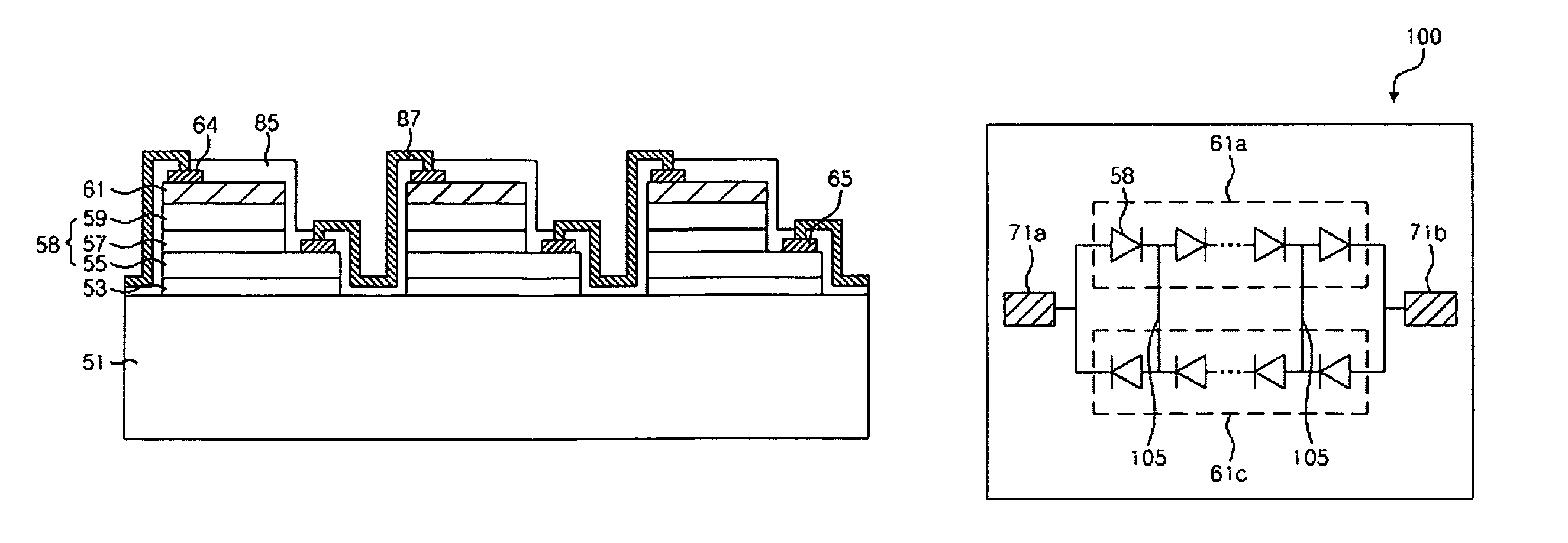
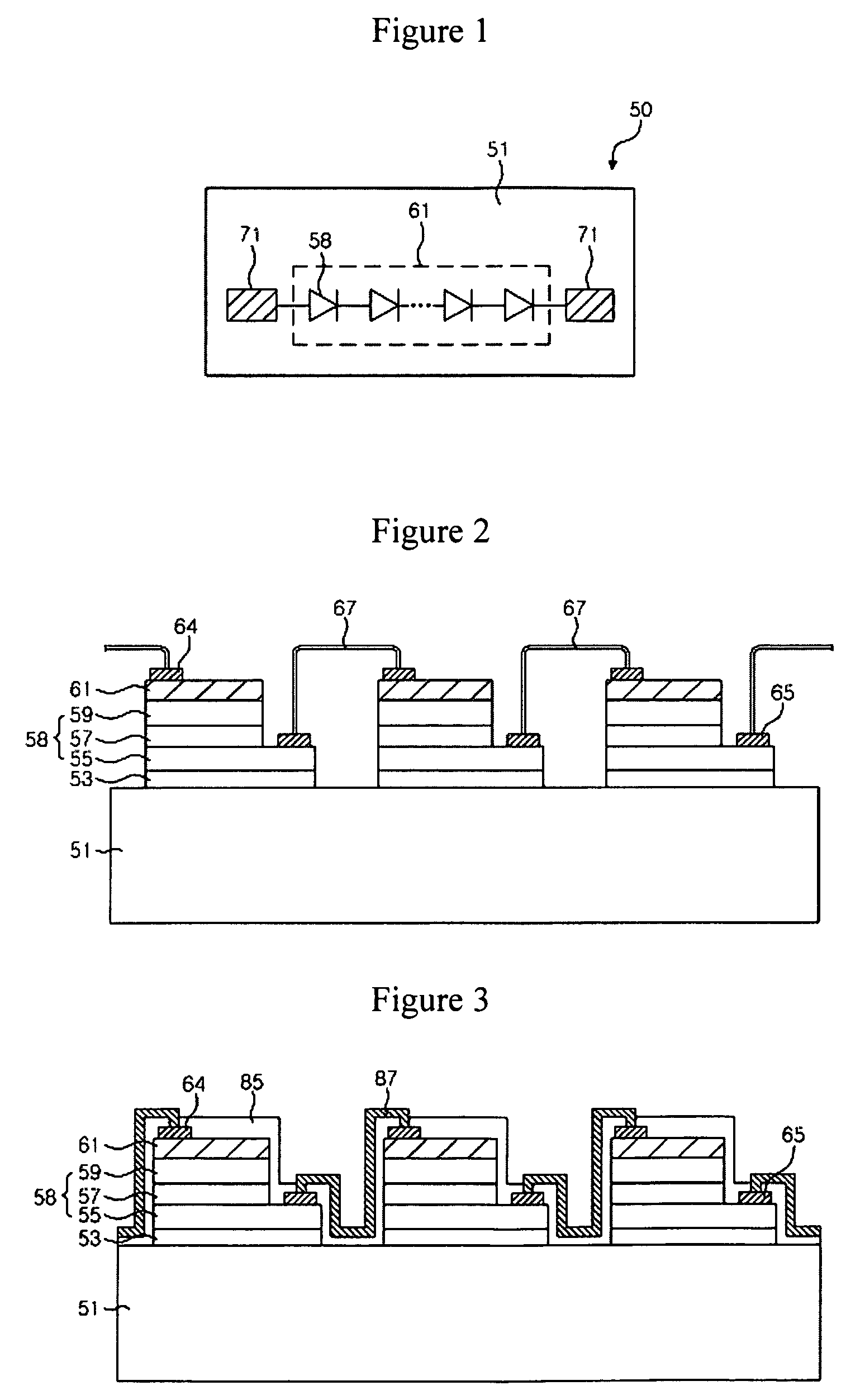
[0029]FIG. 1 is a schematic view illustrating a serial array of light emitting cells according to embodiments of the present invention. Here, the serial arrays are disposed in a single chip 50.

[0030]Referring to FIG. 1, the single chip 50 includes a substrate 51. The substrate 51 may be an insulative substrate or a conductive substrate having an insulating layer ...


PUM


Abstract

An AC light emitting device is disclosed. The AC light emitting device includes at least four substrates. Serial arrays each of which has a plurality of light emitting cells connected in series are positioned on the substrates, respectively. Meanwhile, first connector means electrically connect the serial arrays formed on respective different substrates. At least two array groups each of which has at least two of the serial arrays connected in series by the first connector means are formed. The at least two array groups are connected in reverse parallel to operate. Accordingly, there is provided an AC light emitting device capable of being driven under an AC power source.

Description

CROSS REFERENCE TO RELATED APPLICATIONS[0001]This application is the National Stage of International Application No. PCT / KR2007 / 004268, filed Sep. 5, 2007, and claims priority from and the benefit of Korean Patent Application No. 10-2006-0114553, filed on Nov. 20, 2006, which are both hereby incorporated by reference for all purposes as if fully set forth herein.BACKGROUND OF THE INVENTION[0002]1. Field of the Invention[0003]The present invention relates to a light emitting device, and more particularly, to an AC light emitting device, which can be driven by being connected directly to an AC power source.[0004]2. Discussion of the Background[0005]With the development of GaN based light emitting diodes (LEDs), the GaN based LEDs have considerably changed LED technologies. Currently, the GaN based LEDs are used for various applications such as full-color LED displays, LED traffic lights, white LEDs and the like. Recently, it has been expected that high-efficiency white LEDs will subst...

Claims


Application Information

Patent Timeline
Patent Type & Authority Patents(United States)
IPC IPC(8): H05B37/00H05B44/00
CPCF21K9/00H05B33/0821H01L27/153H01L2224/24137H01L2224/48137H01L2224/49107H05B45/42
Inventor KIM, DAE WONKAL, DAE SUNG
Owner SEOUL VIOSYS CO LTD
Why Eureka
Try Eureka