Eureka AIR delivers breakthrough ideas for toughest innovation challenges, trusted by R&D personnel around the world.

Motor control device, motor drive system, washing machine, air conditioner and method of changing magnetization amount of permanent magnet motor

a technology of permanent magnet motors and control devices, which is applied in the direction of motor/generator/converter stoppers, dynamo-electric converter control, hybrid vehicles, etc., can solve the problems of motors that cannot always be operated with an optimum efficiency, and the actual rotor flux content of motors is uncertain

Active Publication Date: 2012-03-06
KK TOSHIBA
View PDF7 Cites 12 Cited by
  • Summary
  • Abstract
  • Description
  • Claims
  • Application Information

AI Technical Summary

Benefits of technology

[0011]According to each of the above-described arrangements and method, an amount of magnetization of the permanent magnet constituting the rotor of the permanent magnet motor is properly changeable according to a required drive performance.

Problems solved by technology

In this case, however, an actual rotor flux content of the motor is uncertain after the low coercive permanent magnets are magnetized or demagnetized.
Thus, there is a problem that the motor cannot always be operated with an optimum efficiency.

Method used


Image

  • Motor control device, motor drive system, washing machine, air conditioner and method of changing magnetization amount of permanent magnet motor
  • Motor control device, motor drive system, washing machine, air conditioner and method of changing magnetization amount of permanent magnet motor
  • Motor control device, motor drive system, washing machine, air conditioner and method of changing magnetization amount of permanent magnet motor

Examples


Embodiment Construction

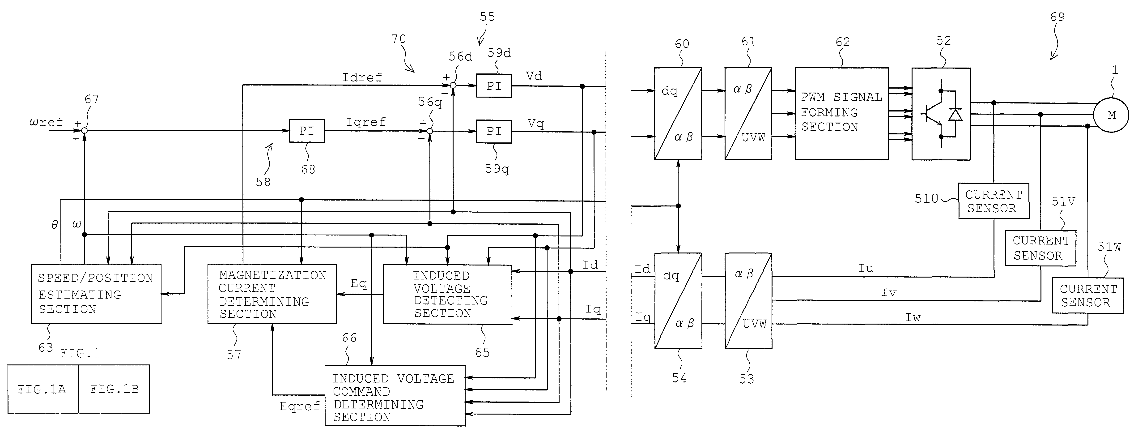
[0021]A first embodiment will be described with reference to FIGS. 1A to 8. FIG. 5 shows a rotor of a permanent magnet motor 1 (outer rotor type brushless motor). The permanent magnet motor 1 is obtained by reconfiguring a motor having the same characteristic as disclosed in patent document 1 into the outer rotor type.

[0022]The permanent magnet motor 1 comprises a stator 2 and the rotor 3 provided around the stator 2 as shown in FIG. 5. The stator 2 comprises a stator core 4 and a stator winding 5. The stator core 4 is made by stacking and swaging a number of steel plates as a stamped-out soft magnetic material. The stator 4 includes an annular yoke 4a and a number of teeth 4b protruding radially from an outer circumference of the yoke 4a. The stator core 4 has a surface covered with a polyethylene terephthalate (PET) resin (molding resin) except for an outer circumference 4b which defines a gap together with an inner circumference of the rotor 3. A plurality of mounts 6 each made f...


PUM


Abstract

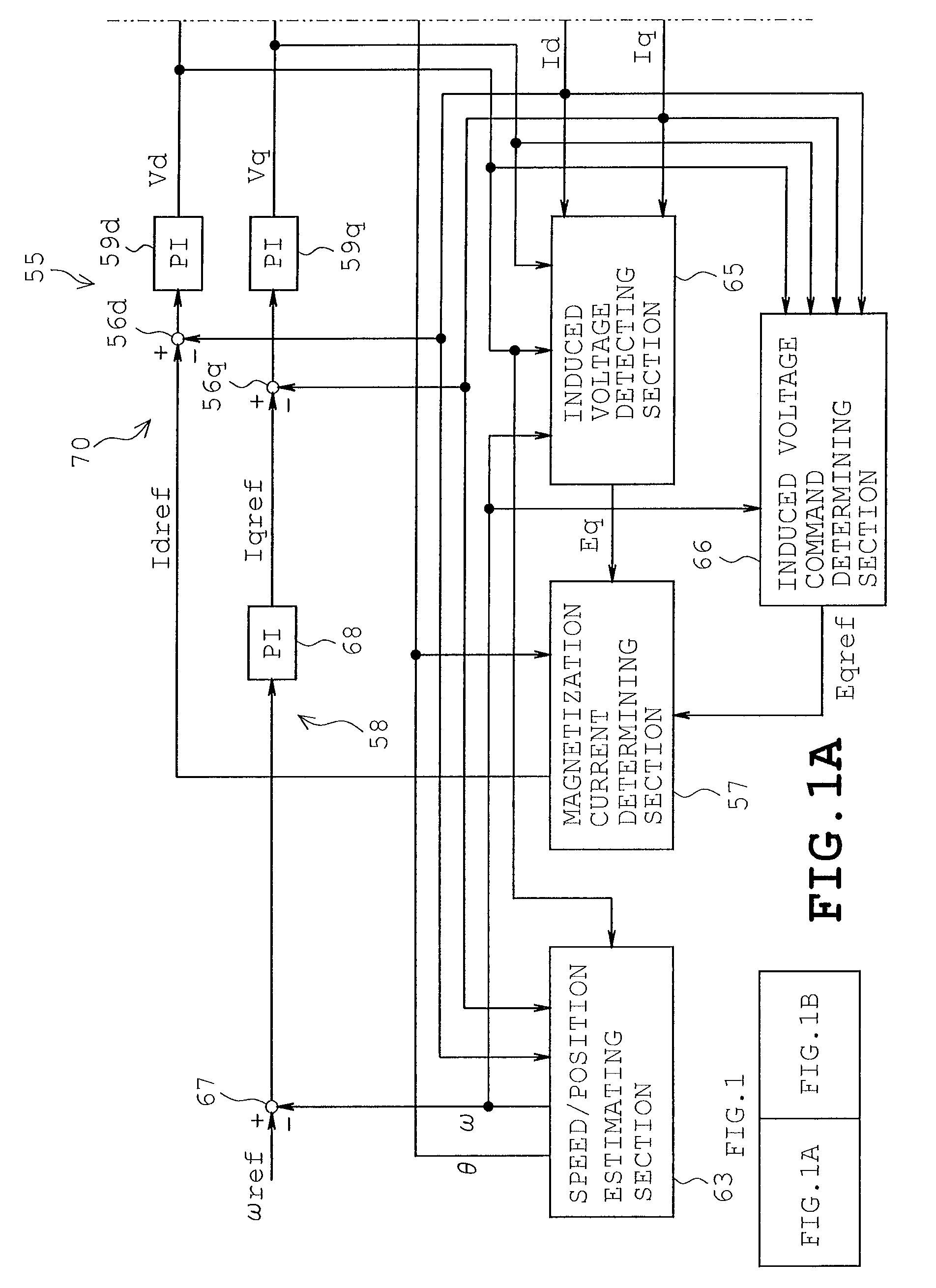
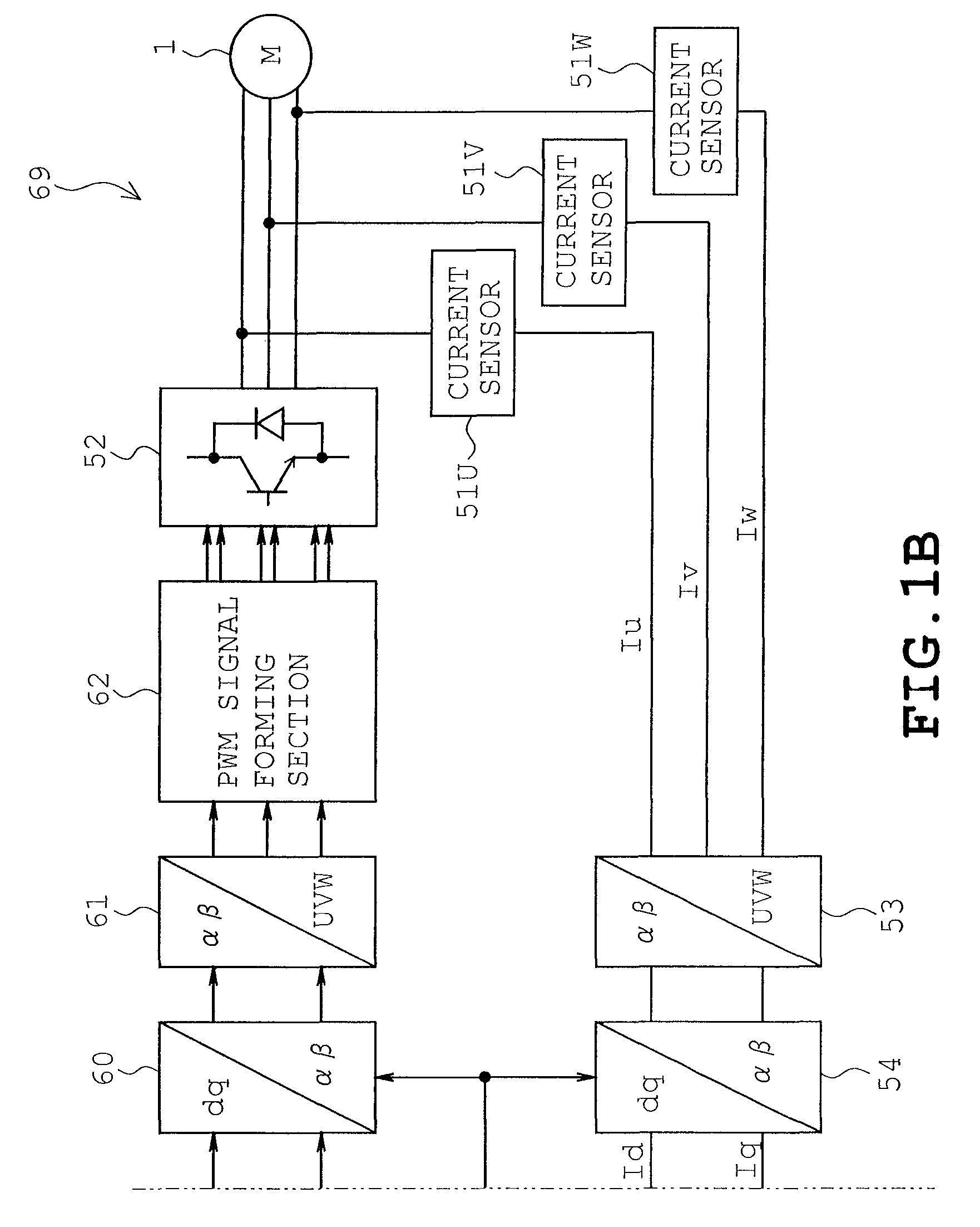
A motor control device includes a magnetization control unit energizing a motor winding to change magnetic flux content of permanent magnet motor, a current detector detecting current supplied to the motor, a vector control unit including a speed / position estimation unit carrying out an operation to estimate a motor rotational speed and rotational position, the vector control unit carrying out a vector control of the motor, an induced voltage detector detecting an induced voltage of the motor based on the rotational speed, motor currents obtained by the vector control unit, output voltages of the drive unit, a winding inductance or the motor constant and a winding resistance, an induced voltage command determining unit determining an induced voltage command based on the motor rotational speed and output torque, and a magnetization current determining unit determining an amount of energization based on the induced voltage of the motor and the induced voltage command.

Description

CROSS-REFERENCE TO RELATED APPLICATIONS[0001]This application is based on and claims the benefit of priority from the prior Japanese Patent Application No. 2008-112437, filed on Apr. 23, 2008, the entire contents of which are incorporated herein by reference.BACKGROUND1. Field[0002]The present invention relates to a motor control device driving a permanent magnet motor in which a rotor includes permanent magnets each having such a low coercive force that an amount of magnetization is changeable, a motor drive system comprising the permanent magnet motor and the motor control device, a washing machine comprising the motor drive system, an air conditioner comprising the motor drive system, and a method of changing a magnetization amount of the permanent magnet motor.2. Related Art[0003]Techniques for variable speed operation of permanent magnet motors ranging from low to high speeds have recently become widespread for the purpose of reducing electric power consumption. A vector contro...

Claims


Application Information

Patent Timeline
Patent Type & Authority Patents(United States)
IPC IPC(8): H02P21/00H02K15/03H02P6/06H02P6/08H02P6/18H02P6/182H02P6/28H02P7/06
CPCH02P21/14
Inventor MAEKAWA, SARINAGAI, KAZUNOBUNITTA, ISAMU
Owner KK TOSHIBA
Why Eureka
Eureka Blog
Learn More