Sensor light

a technology of sensor light and light source, which is applied in the direction of burglar alarm short radiation actuation, lighting and heating apparatus, instruments, etc., can solve the problems of difficult to correctly set the brightness or dusk threshold value, difficult to detect elements accordingly, and often need to be handled with care, so as to improve detection properties and simplify production. , the effect of simple and elegan

Inactive Publication Date: 2012-03-06
STEINEL
View PDF12 Cites 15 Cited by
  • Summary
  • Abstract
  • Description
  • Claims
  • Application Information

AI Technical Summary

Benefits of technology

[0017]Another favorable development of the invention is also that the mirror element which interacts with the sensor (or the individual sensor elements) and is used to achieve the large detection angle can itself be set or adjusted such that the detection range can be set in this way in a simple and elegant manner (for instance by tilting or pivoting individual facets or all facets or segments of the mirror).
[0018]This thus results, in a surprisingly simple and elegant manner, in a sensor light which combines considerably improved detection properties with simplified production and simplified installation and setting properties.

Problems solved by technology

However, the problem with the sensor lights known from the prior art is that these parameters can be set only in the installed state (that is to say on the wall of a house, for instance), with the result that awkward handling is often needed to access the setting elements provided on the sensor light or support unit and / or the sensor unit; it is necessary to use a ladder, for instance, when lights are hung high up.
In addition, it is often difficult to correctly set the brightness or dusk threshold value for activation of the light; this is then often carried out in respective semi-darkness (respectively associated with the disadvantage that the setting elements are accordingly difficult to detect).
Another disadvantage of the apparatuses known from the prior art is that the detection range is extremely inhomogeneous in the circumferential direction, in particular in the case of wide detection angles and the use of a mirror for interacting with an infrared motion sensor; this is due to the fact that, with typically two sensor individual elements of a motion sensor, certain optical irradiation conditions result in the sensor's image being projected onto the sensor setting elements in different ways depending on the circumferential position of a person moving relative to the sensor.
However, since the motion detection signal is based on a difference between the individual signals which are respectively output by the elements, positions exist in the circumferential direction in which both sensor individual elements equally receive infrared images and a usable sensor differential signal is thus not produced, that is to say the motion sensor therefore exhibits a sensitivity range and thus detection range which are extremely inhomogeneous in the environmental direction.

Method used


Image

  • Sensor light
  • Sensor light
  • Sensor light

Examples


Embodiment Construction

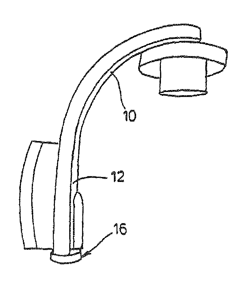
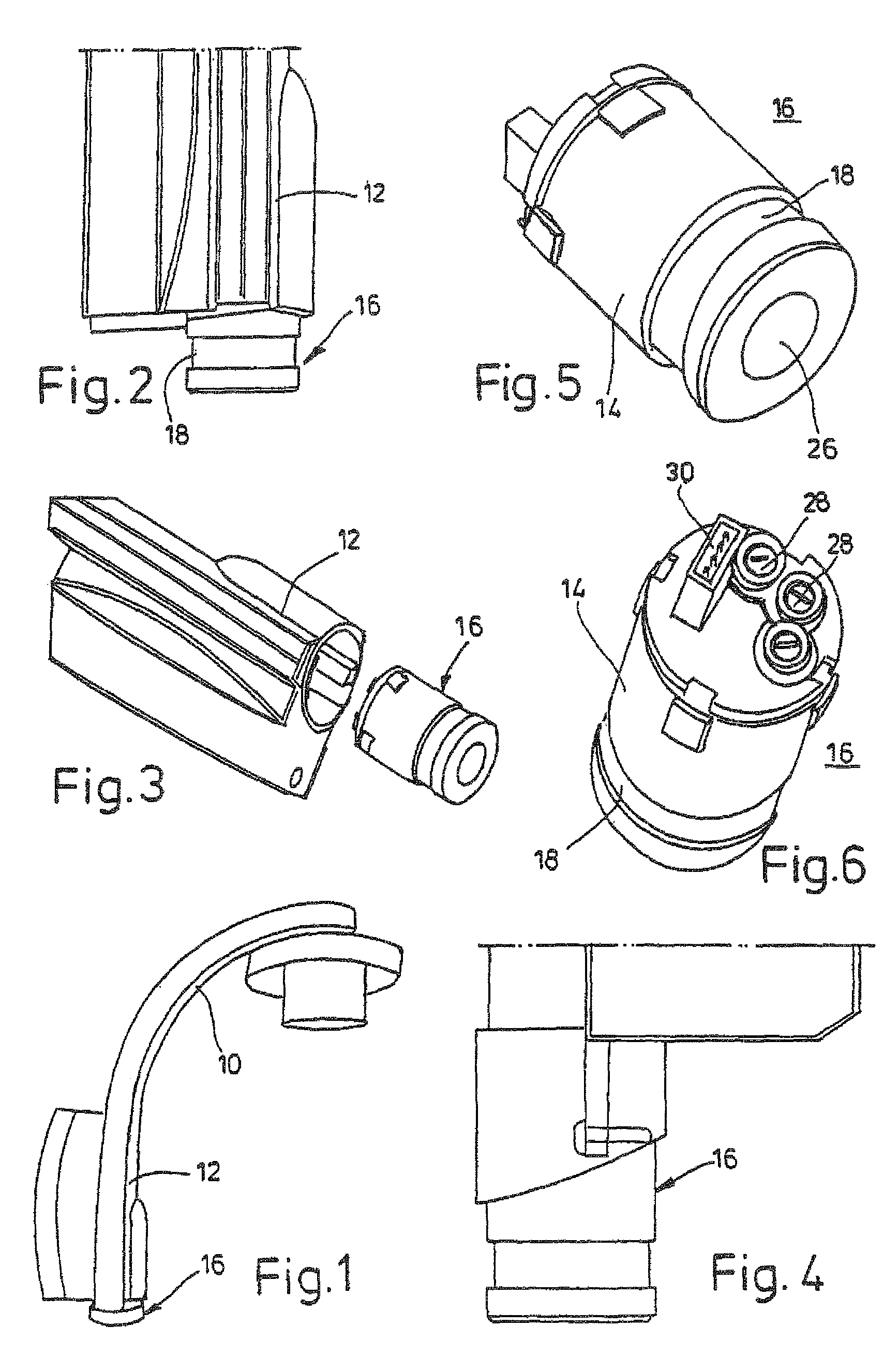
[0026]The sensor light shown in FIG. 1 has a support unit which has an arm 10 and a wall section 12 and is made from a plastic material, a lighting means holder and a carrier for a lampshade (not shown) which surrounds the lighting means holder and thus the lighting means being provided at the end of the arm in an otherwise known manner. At the other end, a motion sensor unit 16 which can be pushed in using a cylindrical sensor housing 14 is provided in the lower region of the arm of the support unit such that it can be removed.

[0027]FIGS. 2 and 3 illustrate the relative relationship between the support unit of the sensor light and the sensor housing; FIG. 2 shows the sensor housing in the pushed-in state, an annular lens section 18 projecting from the housing formed by the support unit in the pushed-in state, whereas the remaining housing section is concealed in the light body. The exploded illustration of FIG. 3 illustrates the pulled-out state.

[0028]The basic design of the sensor...


PUM


Abstract

Sensor light having a light unit which can be activated in response to a sensor output signal from a motion sensor unit (16), and is provided on a support unit (10, 12) for installing the sensor light inside or outside, wherein that the motion sensor unit is modular, can be removed from the support unit when the latter is installed and has at least one actuating element (28) which can be manually operated and can be operated when the motion sensor unit has been removed.

Description

BACKGROUND OF THE INVENTION[0001]The present invention relates to a sensor light according to the precharacterizing clause of the main claim. Such apparatuses are generally known from the prior art and are marketed in large quantities in the form of external lights or garden lights which are controlled by an infrared motion sensor, for instance.[0002]The principle of these lights which are used to form the generic type is that a light unit which is of virtually any desired esthetic configuration and has a lighting means is fastened to a support unit (base unit) which, on the one hand, ensures that the light unit is supplied with electrical power and, on the other hand, enables the sensor light to be mechanically fastened to the wall of a house or enables a fastening position of that kind. In addition, such lights contain a motion sensor system which, typically integrated in the support unit, provides a lens window for a motion sensor that is arranged behind it and is sensitive to in...

Claims


Application Information

Patent Timeline
Patent Type & Authority Patents(United States)
IPC IPC(8): G08B13/00F21V23/04
CPCF21S8/033F21V23/0442G08B13/19
Inventor STEINEL, HEINRICH WOLFGANGMEGGLE, MARTINHERBST, CHRISTOFMOLLER, THOMAS
Owner STEINEL
Why Eureka
Try Eureka