Liquid crystal display device

Inactive Publication Date: 2012-03-13
SHARP KK
View PDF9 Cites 23 Cited by
  • Summary
  • Abstract
  • Description
  • Claims
  • Application Information

AI Technical Summary

Benefits of technology

[0008]In order to overcome the problems described above, preferred embodiments of the present invention to provide a liquid crystal displ

Problems solved by technology

Therefore, light entering from outside to the protruding portion 5a may cause malfunction of the driver IC.
In order to prevent light leakage from outside, it is necessary to attach a very expe

Method used


Image

  • Liquid crystal display device
  • Liquid crystal display device

Examples


Example

[0018]Hereinafter, preferred embodiments of the present invention will be described with reference to the accompanying drawings. It should be noted that, in the following preferred embodiments, a TFT (thin film transistor) liquid crystal display device will be described as an example of the invention.

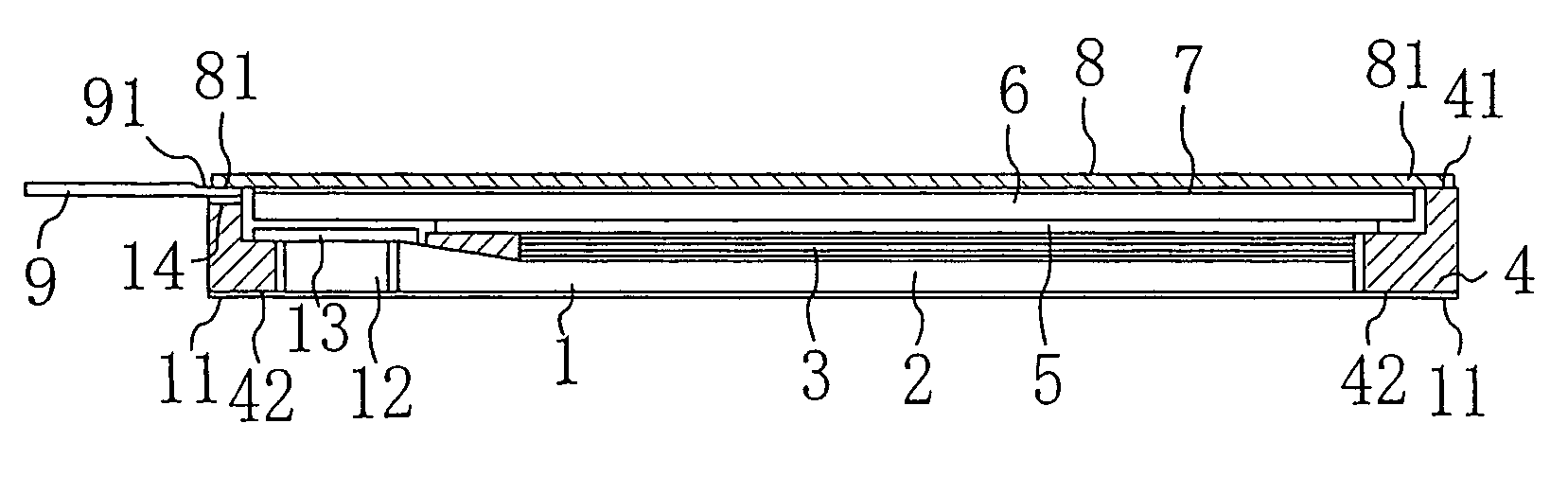
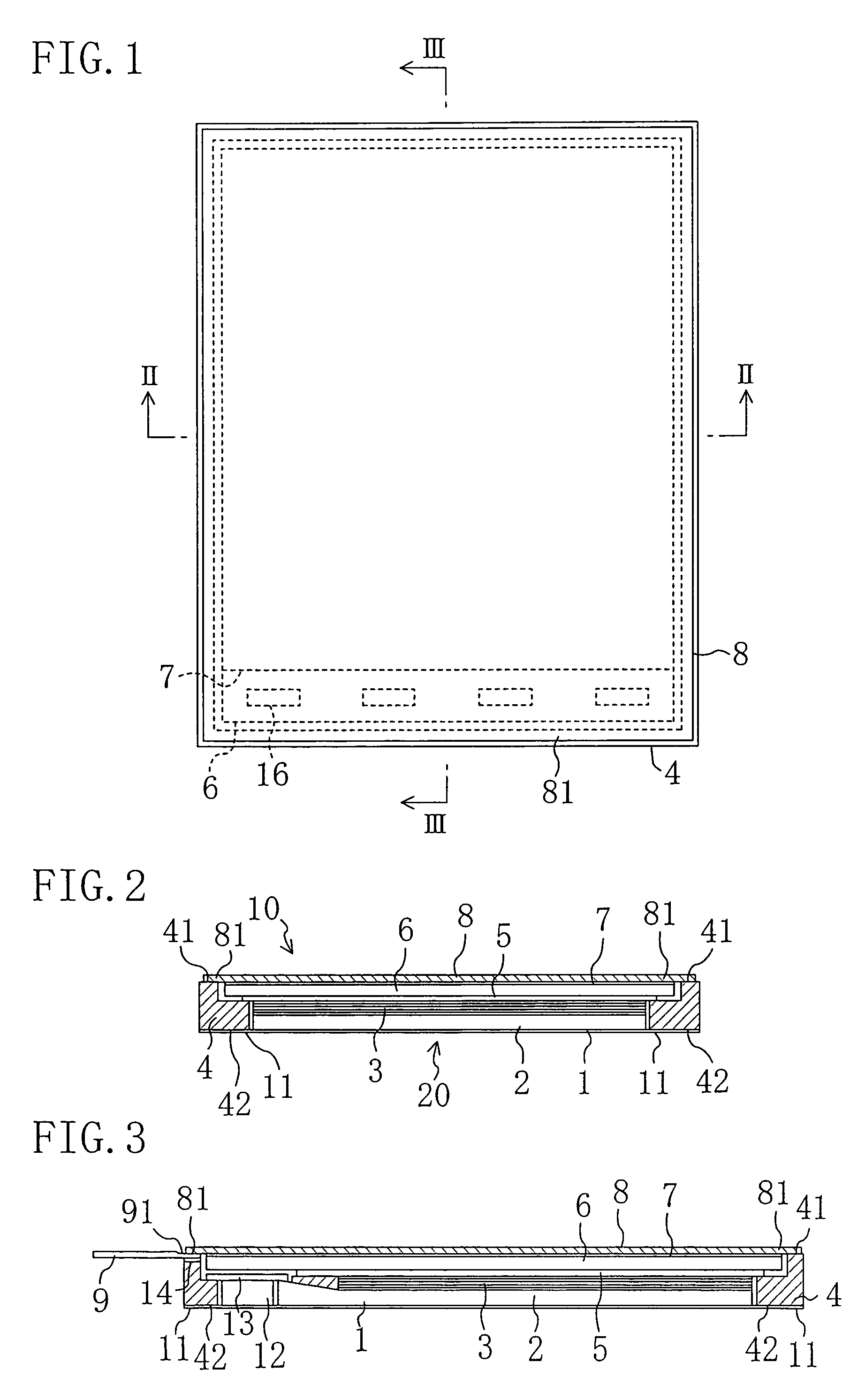
[0019]FIG. 1 is a schematic plan view of a liquid crystal display device of a preferred embodiment of the present invention. FIG. 2 is a cross-sectional view taken along line II-II in FIG. 1. FIG. 3 is a cross-sectional view taken along line III-III in FIG. 1. The liquid crystal display device of the present preferred embodiment includes a liquid crystal display panel 10, a light source 20 provided on the back side of the liquid crystal display panel 10 (on the side opposite to the viewer side), and a frame 4 accommodating the liquid crystal display panel 10 and the light source 20.

[0020]The liquid crystal display panel 10 includes a color filter glass substrate (hereinafter, referred t...


PUM


Abstract

A liquid crystal display device includes at least: a liquid crystal display panel; a light source provided on a back side of the liquid crystal display panel; and a frame accommodating the liquid crystal display panel and the light source and having an upper opening and a lower opening in an upper portion and a lower portion of the frame, respectively. The liquid crystal display panel includes a TFT substrate provided on a side of the light source, a CF substrate, a liquid crystal layer interposed between the TFT substrate and the CF substrate, a thin film driving circuit formed on the TFT substrate for driving the liquid crystal layer, and a front polarizing plate provided on a front surface of the CF substrate and having an overhanging portion overhanging from a periphery of the CF substrate. The front polarizing plate covers the upper opening of the frame and the overhanging portion is fixed to an upper end surface of the frame.

Description

BACKGROUND OF THE INVENTION[0001]1. Field of the Invention[0002]The present invention relates to a liquid crystal display device including at least a liquid crystal display panel, a light source provided on the back side of the liquid crystal display panel, and a frame accommodating the liquid crystal display panel and the light source.[0003]2. Description of the Related Art[0004]Japanese Patent Laid-Open Publication No. 2005-49450 discloses a fixed structure of a liquid crystal display panel and a backlight unit. This fixed structure is characterized in that a polarizing plate attached to a viewing side of the liquid crystal display panel is larger than the outer size of a glass substrate of the liquid crystal display panel and an overhanging portion of the polarizing plate which overhangs from the glass substrate is bonded to an upper end of a frame to fix the liquid crystal display panel and the backlight unit. This fixed structure narrows the frame and improves impact resistance...

Claims


Application Information

Patent Timeline
IPC IPC(8): G02F1/1345G02F1/1333G02F1/1335
CPCG02F1/133308G02F1/133608G02F2001/133317G02F1/133317
Inventor KAWAGUCHI, TAKAFUMIYAMAMOTO, TAKAHIRO
Owner SHARP KK
Why Eureka
Try Eureka