
Method for optimized camera position finding for system with optical character recognition

a technology of optical character recognition and optimized camera position, which is applied in the field of optimizing camera position finding for systems with optical character recognition, can solve the problems of troublesome input of all these data using the numeric keypad, correction of camera alignment, etc., and achieves reliable and fast feedback and efficient detection.

Active Publication Date: 2012-03-13
KOFAX
View PDF6 Cites 3 Cited by
  • Summary
  • Abstract
  • Description
  • Claims
  • Application Information

AI Technical Summary

Benefits of technology

"The present invention provides a method for efficient detection and alignment of a camera sensor to significant data, such as text or barcode data, by using a robust algorithm for predominant alignment line angle detection. The method includes capturing an image of the significant data, contrast adaption, shade compensation, and adaptive binarization to obtain an artifact reduced image. The method also includes detecting image sections with most likely significant data lines, determining distances between adjacent significant data lines, and detecting the predominant alignment line angle. The feedback signal can be an audio or tactile signal, and the method reduces data processing complexity and increases detection speed. The invention provides a reliable and fast feedback enabling users to bring the camera into the right position over the significant data."

Problems solved by technology

If a user wants to use a WAP service or the like then he has to input several data related to the WAP service he / she wishes, so it is often troublesome to input all these data using the numeric keypad.
In particular, visually impaired persons have problems correcting such a camera system for achieving proper alignment with the significant data to be recognized, inasmuch as visually impaired persons cannot see indications on a little display screen or have difficulty following acoustical instructions having additional delays until they are output, so that the correction of the camera alignment can only be made in slow and delayed steps.

Method used


Image

  • Method for optimized camera position finding for system with optical character recognition
  • Method for optimized camera position finding for system with optical character recognition

Examples


Embodiment Construction

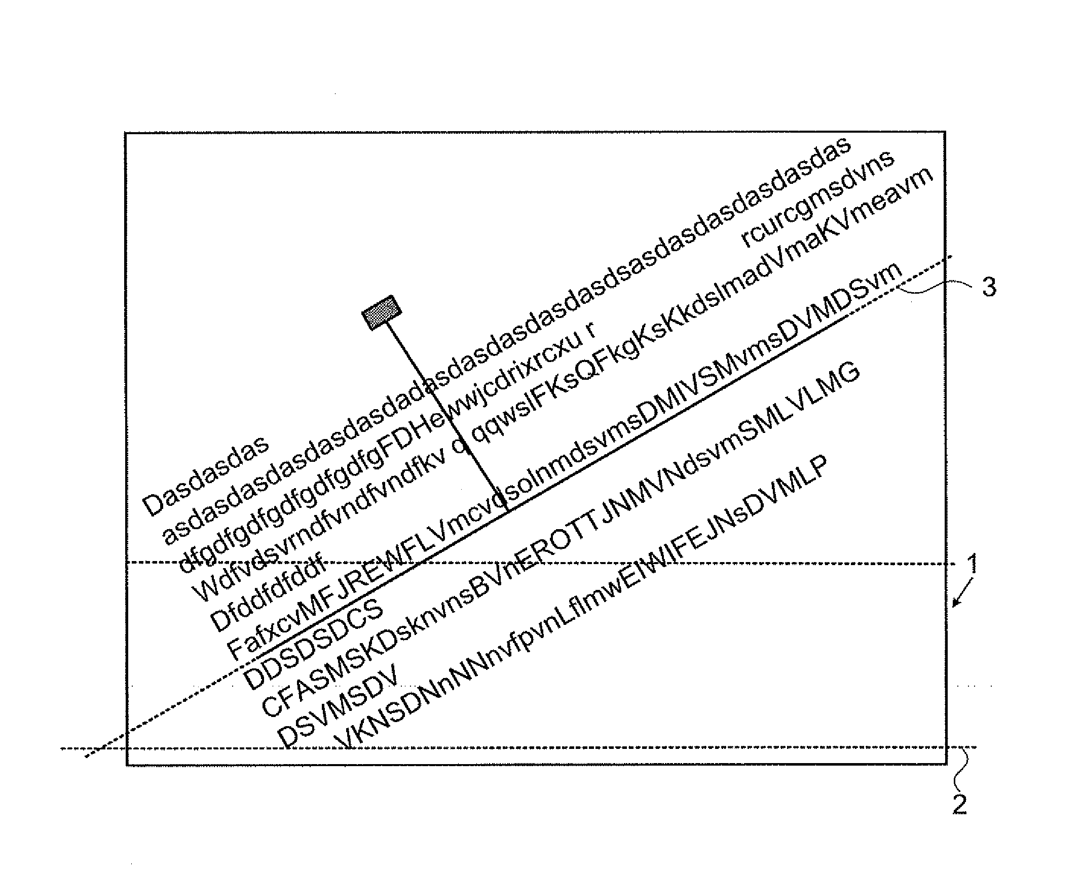
[0033]FIG. 1 shows an image 1 captured by means of a (not shown) camera which is held over a page containing significant data (in the particular embodiment text) that is to be recognized by means of an optical character recognition software (OCR software) and acoustically outputted by means of text-to-speech software (TTS software). Both the OCR software and the TTS software are conventional and familiar to those skilled in the art, and for this reason the description thereof will be omitted. FIG. 1 further shows an alignment line 2 of a (not shown) camera sensor which is identical with an X axis (or a horizontal axis) of the camera sensor. Moreover, FIG. 1 shows a determined predominant alignment line 3 of significant data lines, in particular of shown text lines within the image 1.

[0034]According to the invention there is provided a method determine the predominant alignment line 3 of significant data lines, in particular of shown text lines within the image 1 and to output its de...


PUM


Abstract

The present invention relates to a method for aligning a camera sensor to significant data which is text or barcode data to be recognized comprising the steps of:—capturing an image of the significant data by means of the camera sensor; —detecting a predominant alignment line of the significant data and detecting an angle thereof in relation to a horizontal line of the captured image; —determining image sections within the edge and line enhanced image which contain most likely significant data lines; —selecting a representative image section out of the determined image sections which is aligned with the predominant alignment line; —capturing a following image of the significant data; tracking the representative image section and determining the predominant alignment line out of the representative image section to achieve a fast calculation and audio or tactile feedback of the alignment quality to the user.

Description

BACKGROUND OF THE INVENTION[0001]The present invention relates in general to a method for an optimized camera position finding for systems with optical character recognition. Furthermore, in more detail, the present invention relates to a method for supporting camera based services using a device with an integrated camera, in particular a portable communication device with an integrated camera for taking an image of a page with significant data, in particular with text data in order to recognize the significant data in an automatic way.[0002]Generally speaking, the direction respectively the alignment of the camera sensor with the significant data, in particular text data, is of importance in order to achieve a good automatic recognition e.g. for an optical character recognition (OCR) for text, which is quite sensitive for disalignments. For finding a good camera position with sufficient alignment between the camera sensor and the significant data, in particular text data, it is nec...

Claims


Application Information

Patent Timeline
Patent Type & Authority Patents(United States)
IPC IPC(8): G06K9/00
CPCG06K9/228G06K9/3283G06V30/142G06V30/1478
Inventor GOKTEKIN, CUNEYTTENCHIO, OLIVER
Owner KOFAX
Learn More