Low-cost disposable tourniquet cuff apparatus and method

a low-cost, disposable technology, applied in the field of pneumatic tourniquet cuffs, can solve the problems of increased overall cuff thickness and stiffness, difficult uniform application of cuffs, and high cost of multi-layer cloth/thermoplastic laminates

Active Publication Date: 2012-03-20
WESTERN CLINICAL ENG
View PDF44 Cites 15 Cited by
  • Summary
  • Abstract
  • Description
  • Claims
  • Application Information

AI Technical Summary

Problems solved by technology

Disposable cuffs of the prior art tend to be constructed using exotic materials, such as gel layers, and large amounts of of materials, such as multi-layer cloth / thermoplastic laminates, which are expensive .
Also, the use of these materials in prior-art cuffs has tended to result in a greater overall cuff thickness and stiffness, making the cuffs difficult to apply consistently.
Thicker and stiffer cuffs of the prior art may also degrade performance after cuff application so that higher tourniquet pressures may be required to reliably occlude blood flow; this is undesirable because higher tourniquet pressures are associated in the surgical literature with a higher risk of patient injury.
The absence of an internal stiffening element leads to a reduction of the efficient application of pressure to the limb, and thus leads to an increase in the level of pressure required to stop blood flow past the cuff and into the limb.
Also, the absence of a stiffening element would lead to additional stresses in the outer cuff surface due to less constrained bladder expansion.
The thick outer layer extends to all the cuff edges, and includes an area for sealing the inner layer to the thick outer layer to form the bladder, resulting in the bladder always having a width that is less than the width of the stiffener; this is undesirable because cuffs having narrower bladder widths require higher tourniquet pressures to stop blood flow, and higher tourniquet cuff pressures are associated with a higher risk of patient injury.
Also, this second type of stiffener configuration in cuffs of the prior art, in which the stiffener forms part of the inflatable bladder, greatly limits the extent to which the cuff can expand inwardly into soft tissue when the cuff is pressurized; this limitation increases the pressure required to stop or occlude blood flow in the encircled limb, especially in obese patients and patients having large amounts of soft tissue.
Further, the thick and stiff edges formed at the side edges of these prior-art cuffs may have a tendency to buckle towards the limb, leading to a potential soft-tissue hazard.
This reduces the effectiveness of the stiffener in directing cuff pressure toward the encircled limb across the width of the cuff, and it reduces the extent to which the cuff can expand inwardly when pressurized, thereby making its performance more sensitive to variations in application technique and thereby leading to the possible need for higher tourniquet pressures to stop blood flow past the cuff and into the limb, particularly in patients having large amounts of soft tissue and in patients with poor muscle tone.
Further, an unsecured stiffener within the cuff bladder is not as effective as a secured stiffener in helping to prevent the cuff from twisting or rolling axially along the limb.
In addition, in order to reduce the limitations of performance that are inherent in a cuff having an unsecured stiffener within the inflatable bladder, the width of the stiffener in prior art cuffs has been increased to be as close as possible to the bladder width, which impairs cuff performance and which requires precise alignment of the stiffener during manufacture.
Drawbacks associated with thicker, more rigid cuff materials are discussed above, and many are caused by prior art attempts to combine several cuff elements into a single composite material.
This often results in an increase in thickness and overall rigidity, and a compromise in cuff performance.
Many cuffs of the prior art are susceptible to partial or complete blockage of the gas passageways communicating with the tourniquet cuff.
The manual labor component of cuff assembly is high, especially where multiple sewing and sealing operations are required.
While manufacturing a tourniquet cuff using the design and methods described in the '547 patent may result in a high potential level of automation, the cost of creating the custom manufacturing equipment required to would be high, due to the limited similarities which exist with currently employed cuff manufacturing equipment.

Method used


Image

  • Low-cost disposable tourniquet cuff apparatus and method
  • Low-cost disposable tourniquet cuff apparatus and method
  • Low-cost disposable tourniquet cuff apparatus and method

Examples


Embodiment Construction

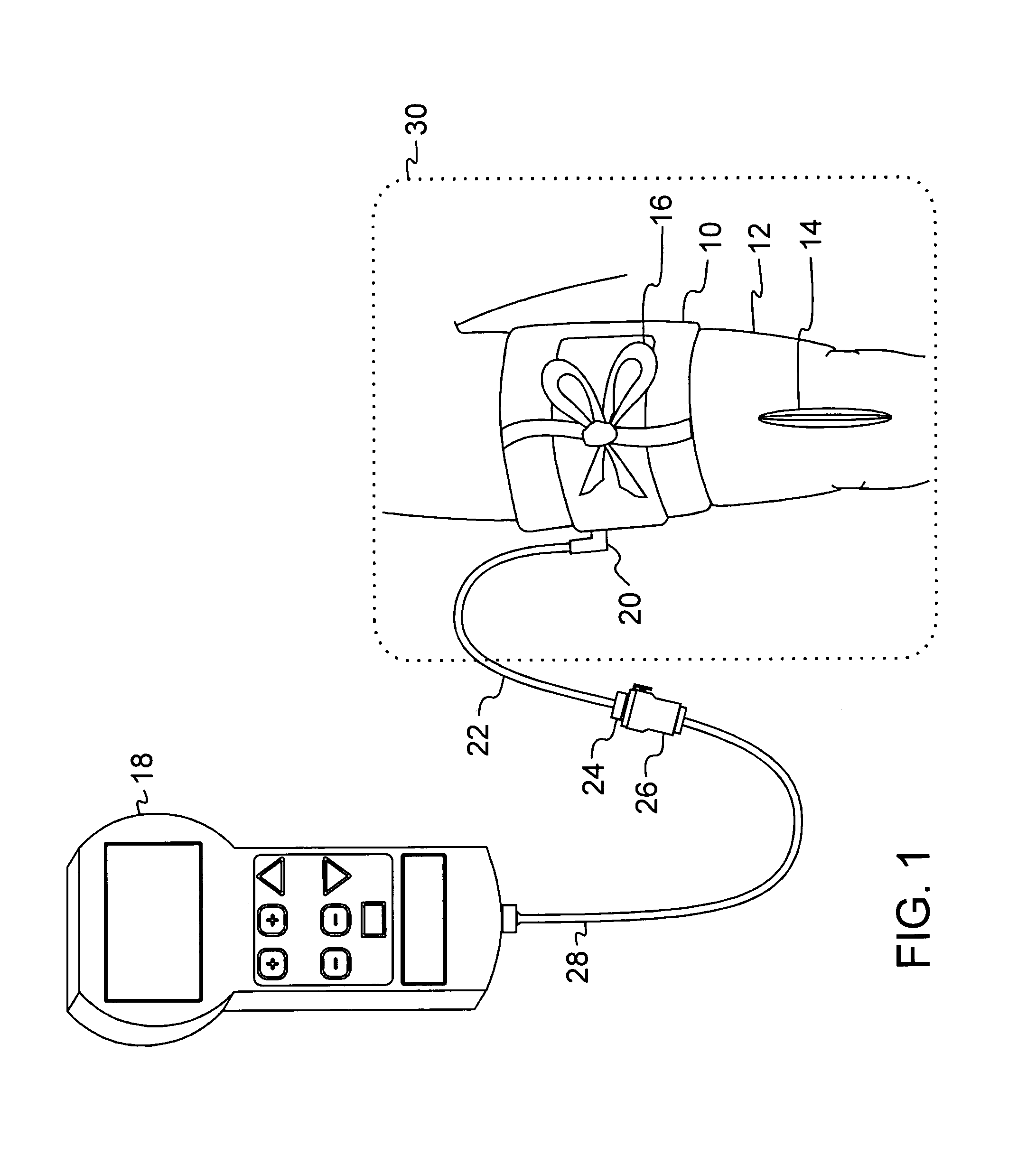
[0026]FIG. 1 is a pictorial representation of the preferred embodiment in a surgical application, showing tourniquet cuff 10 secured circumferentially around patient limb 12 proximal to surgical site 14. Tie strap 16 described further below, is tied as shown in FIG. 1 to help prevent the cuff 10 from sliding proximally or distally on limb 12 when cuff 10 is inflated.

[0027]The inflatable portion of tourniquet cuff 10 completely encircles patient limb 12 and is pneumatically connected to tourniquet instrument 18 via cuff port 20, cuff tubing 22, cuff connector 24, instrument connector 26 and instrument tubing 28. Tourniquet instrument 18 supplies pressurized gas for the inflation of cuff 10 and is capable of inflating cuff 10 to a pressure that will occlude the flow of arterial blood in patient limb 12 distal to cuff 10.

[0028]The perimeter of a sterile surgical field 30 encloses surgical site 14, a portion of patient limb 12, tourniquet cuff 10, and a portion of cuff tubing 22. Cuff t...


PUM


Abstract

Low-cost tourniquet cuff apparatus includes: an inflatable bladder formed of flexible material having a bladder width dimension when the bladder is uninflated and a having a bladder length dimension sufficient for encircling a limb of a surgical patient at a desired location on the limb and for overlapping upon itself, wherein the bladder includes a bladder first inner surface facing a bladder second inner surface along the bladder length dimension and across the bladder width dimension when the bladder is uninflated; securing means for securing the overlapping bladder around the limb at the desired location; port means communicating pneumatically with the inflatable bladder and releasably connectable to a tourniquet instrument for supplying the bladder with pressurized gas; and stiffener means having a predetermined stiffness and having a stiffener width dimension less than the bladder width dimension, wherein the stiffener means is non-releasably attached to the bladder first inner surface within the inflatable bladder. The stiffener means may have a stiffener length dimension that is at least equal to the limb circumference. A method of making the low-cost tourniquet cuff allows the cuff elements to be simply assembled and then sealed in one operation using radio-frequency welding or a similar process.

Description

FIELD OF THE INVENTION[0001]This invention pertains to pneumatic tourniquet cuffs commonly used for stopping arterial blood flow into a portion of a surgical patient's limb to facilitate the performance of a surgical procedure, and for facilitating intravenous regional anesthesia.BACKGROUND OF THE INVENTION[0002]Typical surgical tourniquet systems of the prior art include a tourniquet cuff which encircles the limb of a surgical patient, and a tourniquet instrument which is releasably connected to the tourniquet cuff through a length of tubing, establishing a sealed gas passageway between the cuff and instrument. Tourniquet cuffs typically include an inflatable portion, which encircles the limb of a patient at a desired location, and is connected through a cuff port to a tourniquet instrument through one or more sections of tubing.[0003]The tourniquet instrument contains a pressurized gas source which is used to inflate and regulate the pressure in the tourniquet cuff above a minimum...

Claims


Application Information

Patent Timeline
Patent Type & Authority Patents(United States)
IPC IPC(8): A61B17/00
CPCA61B17/1322A61B17/135A61B2017/0023
Inventor MCEWEN, JAMES A.JAMESON, MICHAELGLINZ, KENNETH LUPWARD, ALLEN J
Owner WESTERN CLINICAL ENG
Why Eureka
Try Eureka