Exhaust gas purification device of internal combustion engine

a technology of exhaust gas purification device and internal combustion engine, which is applied in electrical control, auxillary pretreatment, separation process, etc., can solve the problems of clogging of dpf, melting of dpf, and breakage of dpf, and achieve the effect of improving the performance of suppression of excessive temperature increase of particulate filters

Active Publication Date: 2012-03-20
DENSO CORP
View PDF21 Cites 3 Cited by
  • Summary
  • Abstract
  • Description
  • Claims
  • Application Information

AI Technical Summary

Benefits of technology

[0016]It is an object of the present invention to provide an exhaust gas purification device of an internal combustion engine capable of avoiding excessive temperature increase of a DPF by suitably selecting a method of increasing an exhaust gas flow rate to pass a heat of the DPF downstream or a method of reducing an intake air to suppress combustion of particulate matters during combustion of the particulate matters in the DPF.

Problems solved by technology

However, the DPF will be clogged if the particulate matters only continue to deposit in the DPF.
If temperature increases excessively during the DPF regeneration, problems such as melting of the DPF or breakage of the DPF can occur.
For example, if no-injection operation (i.e., operation of injecting no fuel into an engine) occurs when the temperature of the DPF is high during the regeneration of the DPF and the particulate matter deposition quantity in the DPF is large, an intake quantity decreases rapidly, so transmission of a heat inside the DPF to a downstream portion by exhaust gas is hindered.
Accordingly, the heat stays and accumulates inside the DPF, thereby increasing the risk of the excessive temperature increase of the DPF.
That is, a gas volume enough to pass the heat of the DPF downstream cannot be acquired when the engine rotation speed is low, so sufficient cooling effect cannot be acquired and the excessive temperature increase cannot be suppressed.
However, according to the knowledge of the inventors, if the method of Patent document 2 is used when the engine rotation speed is high, there can occur a problem that negative pressure in the cylinder in an intake stroke becomes excessive and oil loss via the piston ring from a cylinder wall surface occurs.
However, such the technology has not been proposed in conventional technologies including Patent documents 1 and 2.

Method used


Image

  • Exhaust gas purification device of internal combustion engine
  • Exhaust gas purification device of internal combustion engine
  • Exhaust gas purification device of internal combustion engine

Examples


first embodiment

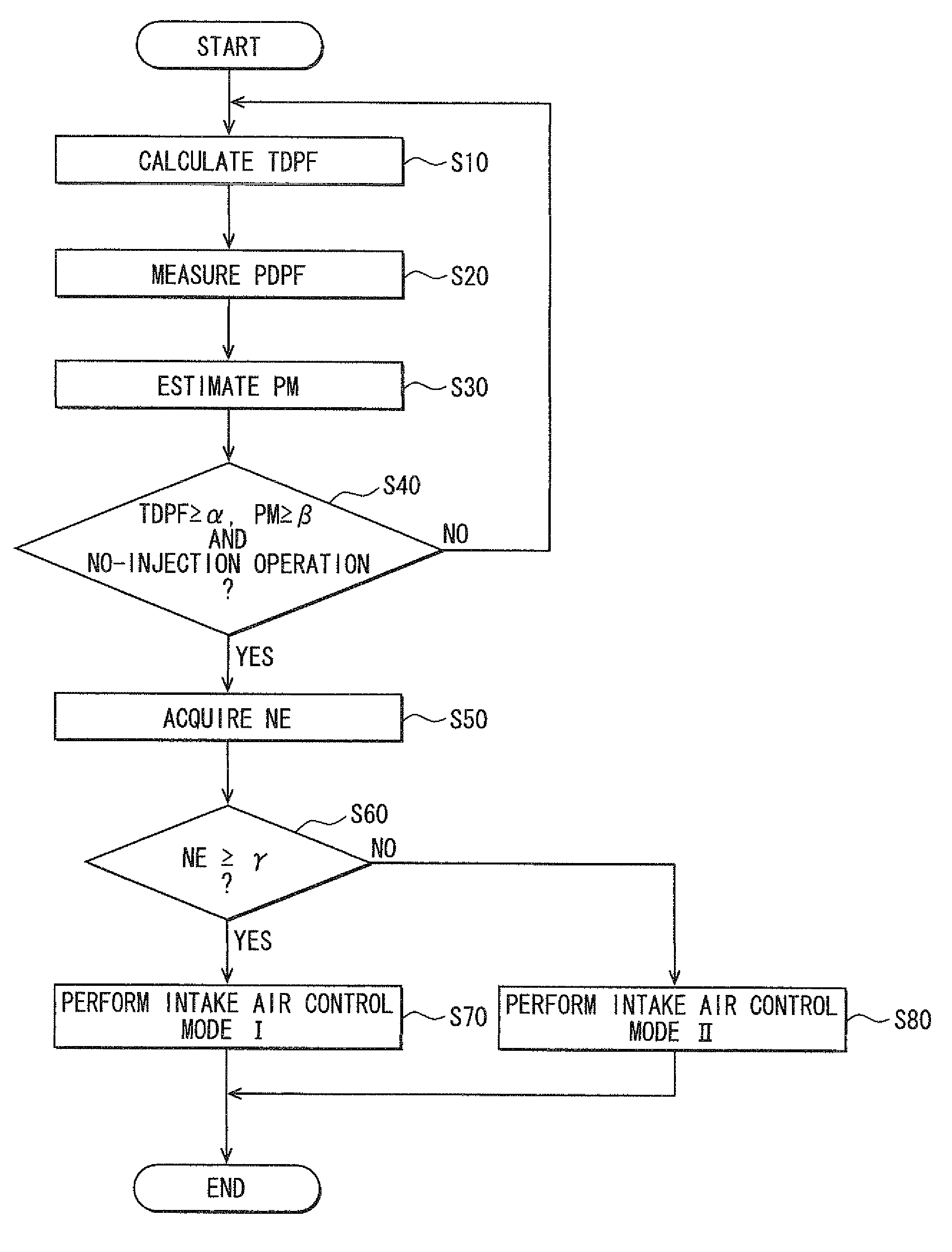
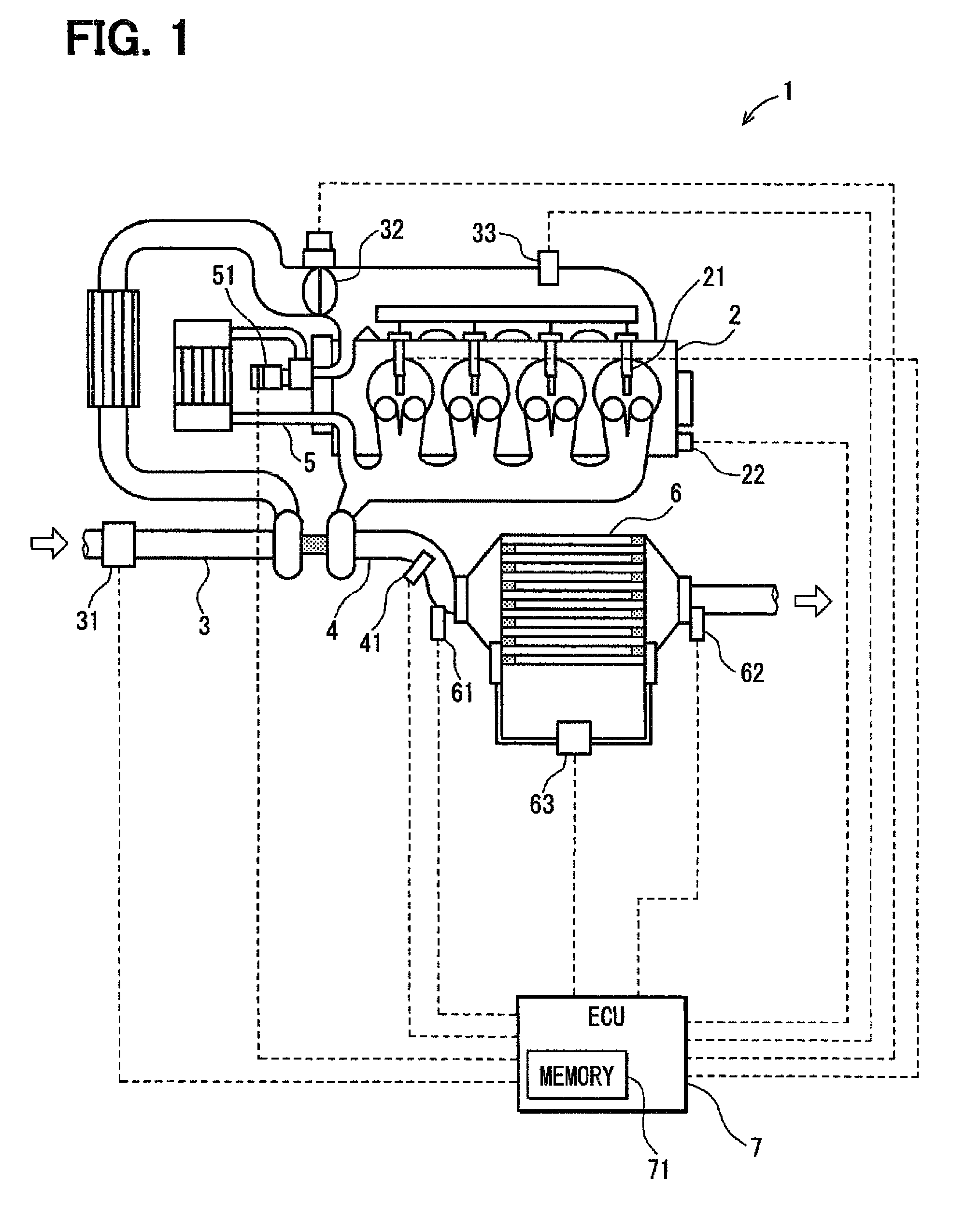
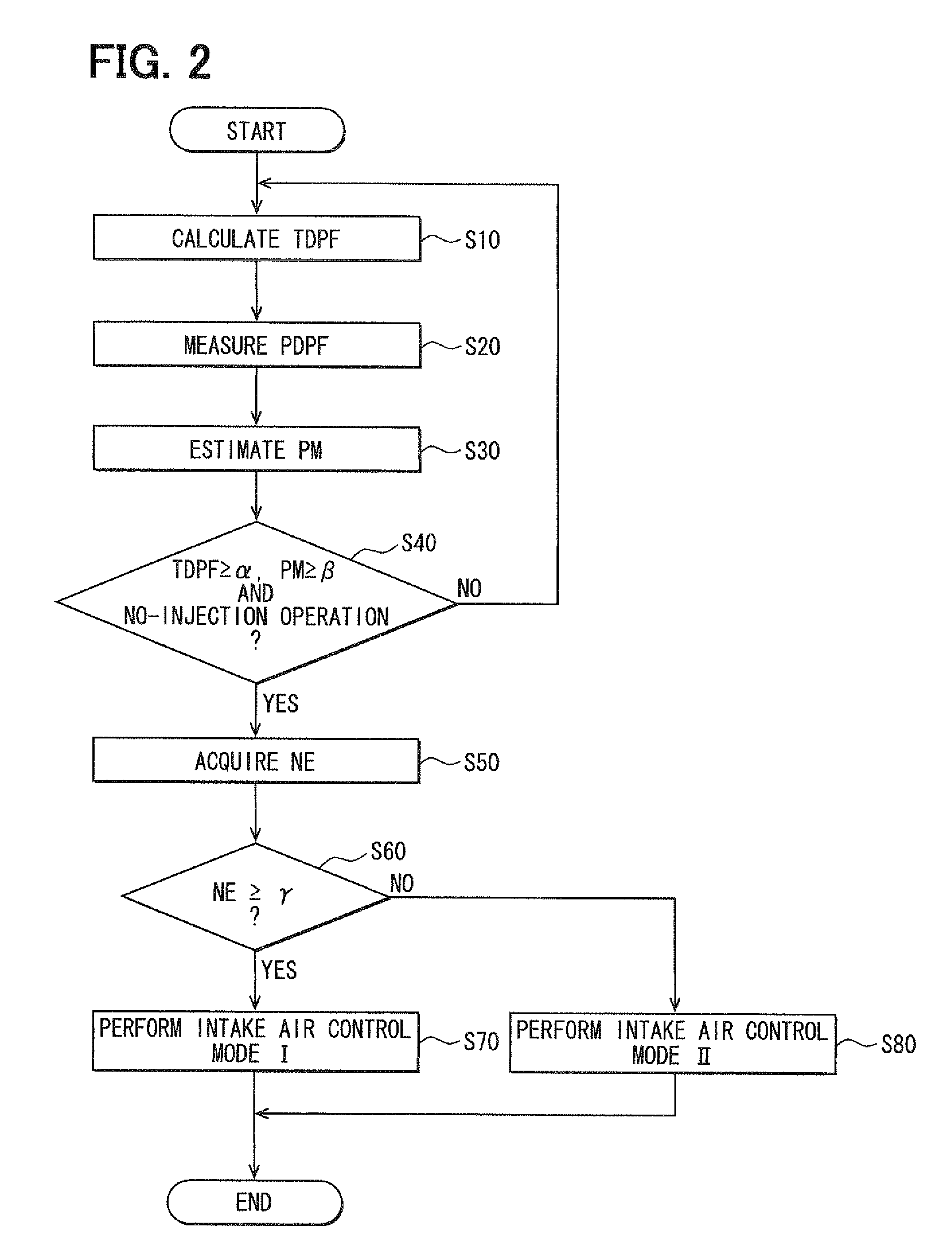
[0048]Hereafter, embodiments of the present invention will be described with reference to the drawings. FIG. 1 is a schematic diagram showing a device configuration of an exhaust gas purification device 1 of an internal combustion engine according to the present invention.

[0049]The exhaust gas purification device 1 according to the present embodiment is applied to a four-cylinder diesel engine 2 (hereafter, referred to simply as an engine), for example. The internal combustion engine and the exhaust gas purification device 1 shown in FIG. 1 mainly consist of an engine 2, an intake pipe 3, an exhaust pipe 4, and an exhaust gas recirculation pipe 5.

[0050]An air (a fresh air, an intake air) is supplied to the engine 2 through the intake pipe 3. An airflow meter 31 and an intake throttle valve 32 are arranged in the intake pipe 3. The airflow meter 31 measures an air intake quantity. A mass flow rate per unit time may be used as the intake quantity. The intake quantity supplied to the e...

second embodiment

[0074]The meaning of the processing of S61 of the second embodiment will be explained using FIG. 4. In FIG. 4, an axis of abscissas indicates the engine rotation speed NE and an axis of ordinate indicates the intake quantity G. Two solid lines 201, 202 indicate characteristics of the intake quantity G and the engine rotation speed NE in the case where the intake air control modes I, II are used respectively. The solid lines 201, 202 are characteristics decided for each of individual devices.

[0075]If the intake air control mode I is selected and the operation is changed from the normal operation (non-idle operation) to the idle operation as shown in FIG. 8, an indication point indicating the intake quantity G and the engine rotation speed NE moves on the solid line 201 from the upper right to the lower left of the graph of FIG. 4. If the intake air control mode II is selected and the operation is changed from the normal operation (non-idle operation) to the idle operation as shown in...

third embodiment

[0083]The meaning of the processing of S62 of the third embodiment will be explained using FIG. 6. In FIG. 6, an axis of abscissas indicates the engine rotation speed NE and an axis of ordinate indicates the intake pressure P. Two solid lines 211, 212 indicate characteristics of the intake pressure P and the engine rotation speed NE in the case where the intake air control modes I, II are used respectively. The solid lines 211, 212 are characteristics decided for each of individual devices.

[0084]If the intake air control mode I is selected and the operation is changed from the normal operation (non-idle operation) to the idle operation as shown in FIG. 8, an indication point indicating the values of the intake pressure P and the engine rotation speed NE moves on the solid line 211. If the intake air control mode II is selected and the operation is changed from the normal operation (non-idle operation) to the idle operation as shown in FIG. 8, the indication point indicating the valu...


PUM

PropertyMeasurementUnit
temperatureaaaaaaaaaa
deposition quantityaaaaaaaaaa
rotation speedaaaaaaaaaa

Abstract

A first intake air control mode of setting an intake throttle valve to (or close to) a fully-opened state and setting an EGR valve to (or close to) a fully-closed state is performed when DPF temperature and a particulate matter deposition quantity are greater than corresponding predetermined values respectively, a no-injection operation state exists, and engine rotation speed is higher than a corresponding predetermined value. A second intake air control mode of setting the intake throttle valve to (or close to) a fully-closed state and setting the EGR valve to (or close to) a fully-opened state is performed when the DPF temperature and the particulate matter deposition quantity are greater than the corresponding predetermined values respectively, the no-injection operation state exists, and the engine rotation speed is lower than the corresponding predetermined value.

Description

CROSS REFERENCE TO RELATED APPLICATION[0001]This application is based on and incorporates herein by reference Japanese Patent Application No. 2008-6922 filed on Jan. 16, 2008.BACKGROUND OF THE INVENTION[0002]1. Field of the Invention[0003]The present invention relates to an exhaust gas purification device of an internal combustion engine.[0004]2. Description of Related Art[0005]Today, awareness of environmental conservation is increasing and excellent exhaust gas purification performance of an internal combustion engine is required. Specifically, for further spread of diesel engines, removal of exhaust particulates (i.e., particulate matters) such as black smoke discharged from the engine is important. In many cases, a diesel particulate filter (DPF) is equipped in an exhaust pipe for removing the particulate matters.[0006]Since the DPF collects the particulate matters in the exhaust gas, a major part of the particulate matters is removed. However, the DPF will be clogged if the par...

Claims


Application Information

Patent Timeline
Patent Type & Authority Patents(United States)
IPC IPC(8): B01D46/46
CPCF02D9/02F02D41/0055F02D41/029F02B29/0406F02D2041/0017F02M25/0707F02M25/0713F02M25/0718F02M25/0727Y02T10/47Y02T10/42Y10S55/30F01N2610/1453F01N2610/146F02M26/05F02M26/10F02M26/15F02M26/23Y02T10/40
Inventor YAHATA, SHIGETOSOGA, TSUTOMUKUBOSHIMA, TSUKASA
Owner DENSO CORP
Why Eureka
Try Eureka