Trajectory processing apparatus and method

a technology of trajectory processing and processing apparatus, which is applied in the direction of image analysis, image enhancement, instruments, etc., can solve the problem of difficult one-way tracking and achieve the effect of avoiding the problem of tracing the movement of one customer in the entire region of the stor

Inactive Publication Date: 2012-03-20
TOSHIBA TEC KK
View PDF19 Cites 10 Cited by
  • Summary
  • Abstract
  • Description
  • Claims
  • Application Information

AI Technical Summary

Problems solved by technology

However, according to the current image processing technology, even if an entire area in a store is shot without blind spots, tracing movement of one customer in the entire region in the store as one trajectory is very difficult.

Method used


Image

  • Trajectory processing apparatus and method
  • Trajectory processing apparatus and method
  • Trajectory processing apparatus and method

Examples


first embodiment

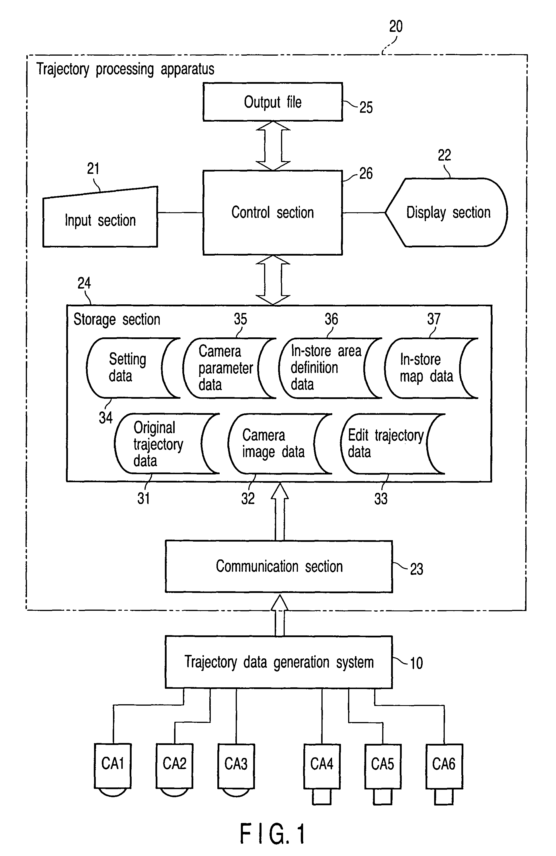
[0030]This embodiment includes six cameras CA1 to CA6, a trajectory data generation system 10, and a trajectory processing apparatus 20 as shown in a block diagram of FIG. 1.

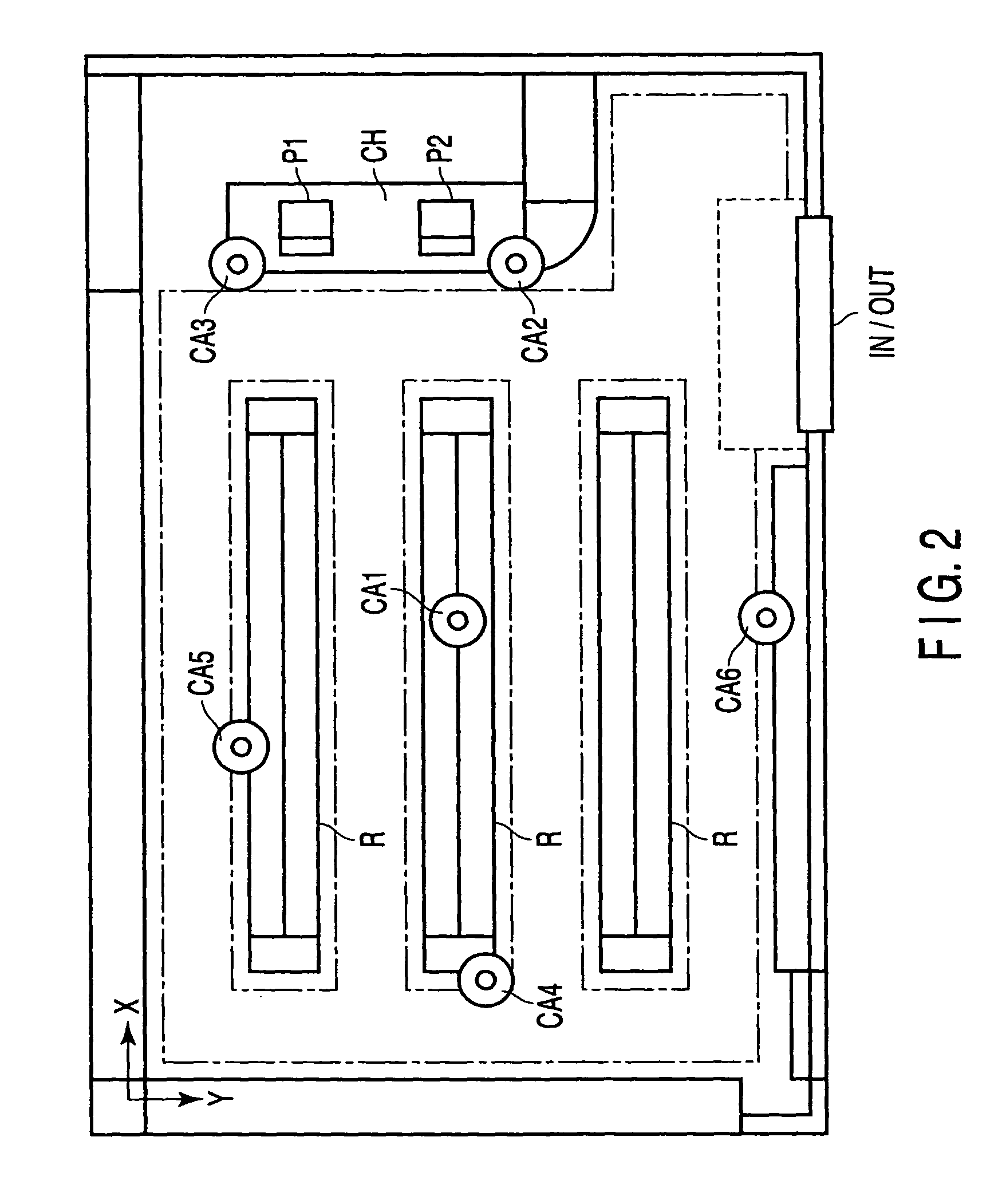
[0031]In regard to the respective cameras CA, one camera (CA1) is disposed on a ceiling in a central portion in a store, two cameras (CA2 and CA3) are disposed on the ceiling near a checkout counter CH where POS (Point Of Sales) terminals 11a and 11b are placed, and three cameras (CA4, CA5, and CA6) are disposed on the ceiling at three positions on an inner side in the store and right and left wall sides with respect to the checkout counter CH.

[0032]Of these cameras, the cameras CA1, CA2, and CA3 are cameras each using a fish-eye lens, i.e., so-called fish-eye cameras, and the cameras CA4, CA5, and CA6 are cameras each having an omnidirectional mirror, i.e., so-called omnidirectional cameras.

[0033]It is to be noted that the number of the cameras is not restricted to six, and it may be three to five or seven or a...

second embodiment

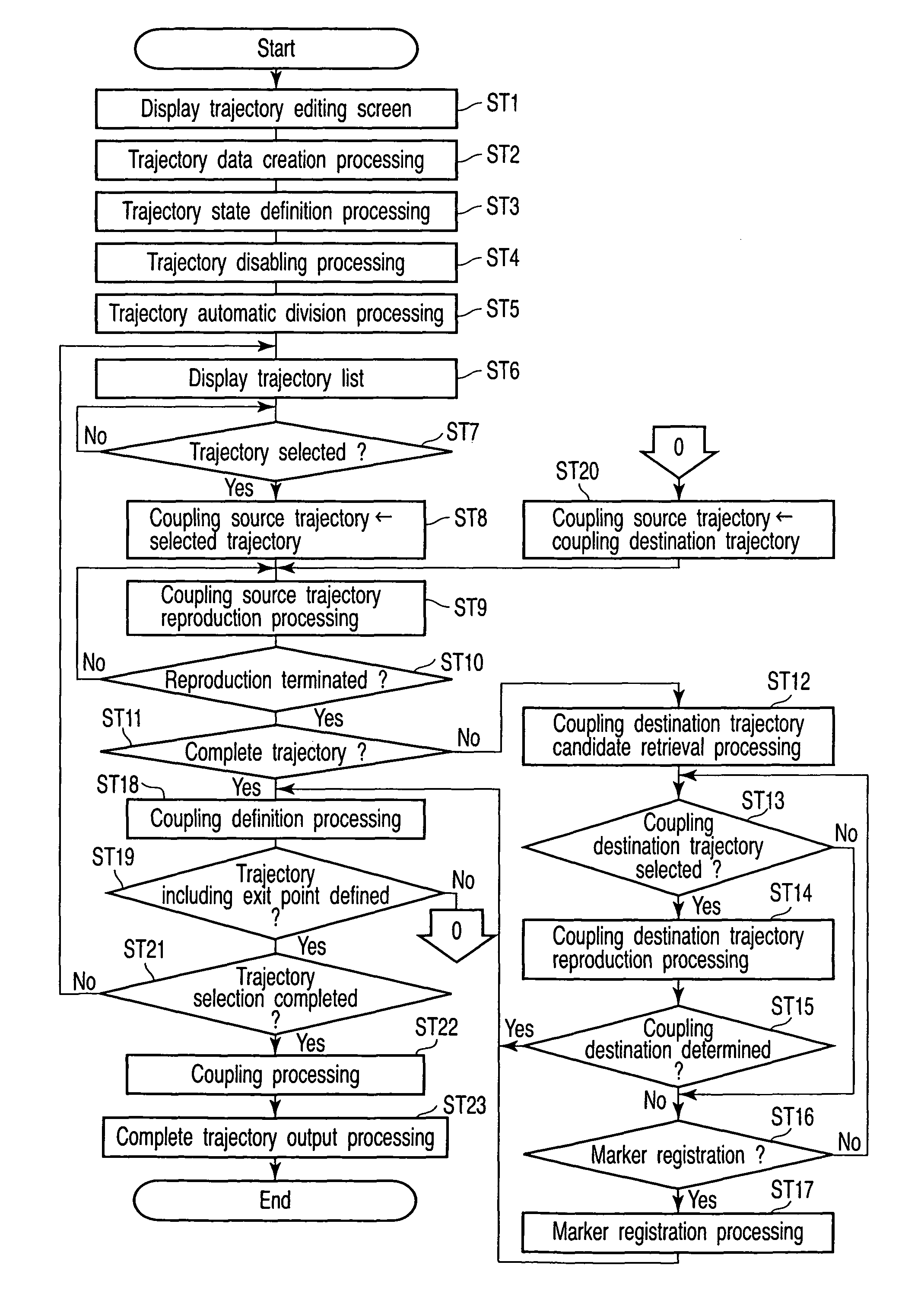
[0209]A second embodiment in which the coupling source trajectory reproduction processing is changed will now be explained. A flowchart of FIG. 17 shows a processing procedure of this reproduction processing.

[0210]It is to be noted that, in the second embodiment, a division point flag S is added to one piece of index information constituting original trajectory data. Any other structures are the same as those in the first embodiment.

[0211]First, a control section 26 reads edit trajectory data having a set coupled source trajectory ID from an edit trajectory database 33 in step 141. Further, top index information is acquired from this edit trajectory data.

[0212]Then, the control section 26 searches an original trajectory database 31 to acquire original trajectory data having set shooting date and time information T of the obtained index information in step 142. Furthermore, an in-store coordinate (X, Y, H) is acquired from the obtained index information in step 143. Moreover, in step...


PUM


Abstract

A trajectory processing apparatus comprises a trajectory database configured to store a position coordinate of a movable body detected from a camera image in association with data that specifies the camera image from which the movable body is detected, and a camera image database configured to store the camera image. A control section fetches the position coordinate of the movable body and the specifying data for the camera image from which the movable body is detected from the trajectory database. Further, the position coordinate of the movable body fetched from the trajectory database is displayed in a display section as a trajectory of the movable body. Furthermore, the control section acquires from the camera image database the camera image specified by the specifying data fetched from the trajectory database. Moreover, this camera image is displayed in the display section.

Description

CROSS-REFERENCE TO RELATED APPLICATIONS[0001]This application is based upon and claims the benefit of priority from prior Japanese Patent Applications No. 2007-170703, filed Jun. 28, 2007; No. 2007-170704, filed Jun. 28, 2007; No. 2007-170705, filed Jun. 28, 2007; No. 2007-170706, filed Jun. 28, 2007; and No. 2007-283727, filed Oct. 31, 2007, the entire contents of all of which are incorporated herein by reference.BACKGROUND OF THE INVENTION[0002]1. Field of the Invention[0003]The present invention relates to a trajectory processing apparatus and method that process a trajectory indicative of a route of a movable body, e.g., a person who moves in a monitored region.[0004]2. Description of the Related Art[0005]There has been conventionally known a trajectory processing apparatus disclosed in JP-A 2006-350751 (KOKAI). This apparatus has a picture database, a sales information database, a trajectory conversion processing section, and a trajectory database. In the picture database, pict...

Claims


Application Information

Patent Timeline
Patent Type & Authority Patents(United States)
IPC IPC(8): G06K9/00
CPCG06T7/2093G06T2207/10016G06T2207/30196G06T2207/30241G06T7/292
Inventor TAKAHATA, MASAMIKOISO, TAKASHINARAHASHI, MASAKIIKUMI, TOMONORI
Owner TOSHIBA TEC KK
Why Eureka
Try Eureka