Dynamic ride matching system

a technology of dynamic ride and matching system, applied in the field of transportation management system, to achieve the effect of accurate measuremen

Active Publication Date: 2012-03-20
UNIV OF SOUTH FLORIDA
View PDF8 Cites 84 Cited by
  • Summary
  • Abstract
  • Description
  • Claims
  • Application Information

AI Technical Summary

Benefits of technology

The ride matching method described in this patent is unique in its ability to handle trips with schedules that cannot be easily expressed in terms of a simple recurrence pattern. It can handle one-time and occasional trips, and uses spatial analysis techniques to locate matches. Specifically, the method uses a shortest path solver to search along the path of a user's trip and calculate the driving distance between the user and a match, providing a more accurate measurement than the straight-line distance used by other methods.

Problems solved by technology

The technical problem addressed in this patent text needs to be identified by a senior R&D person who has read it through.

Method used


Image

  • Dynamic ride matching system
  • Dynamic ride matching system
  • Dynamic ride matching system

Examples


Embodiment Construction

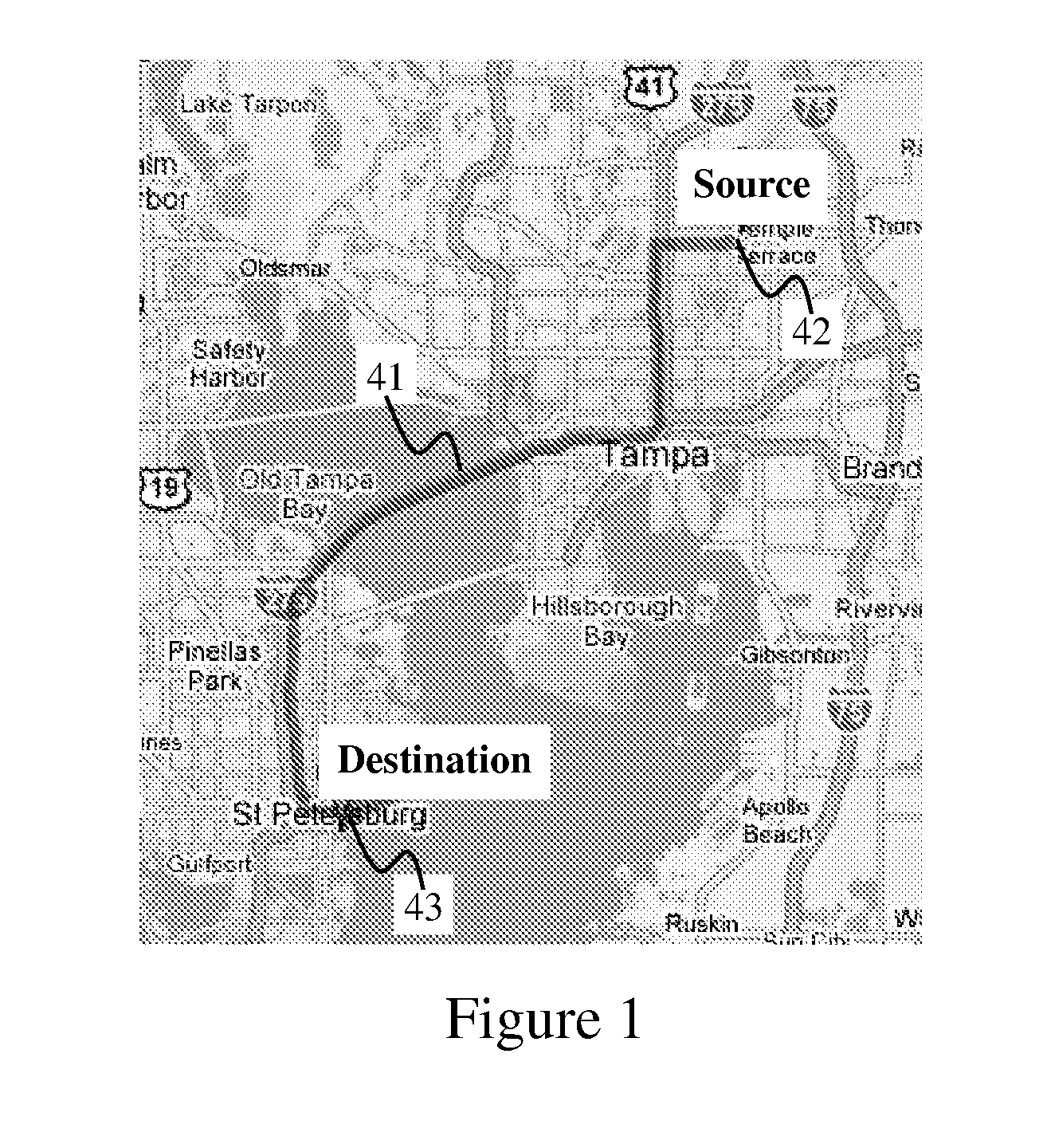
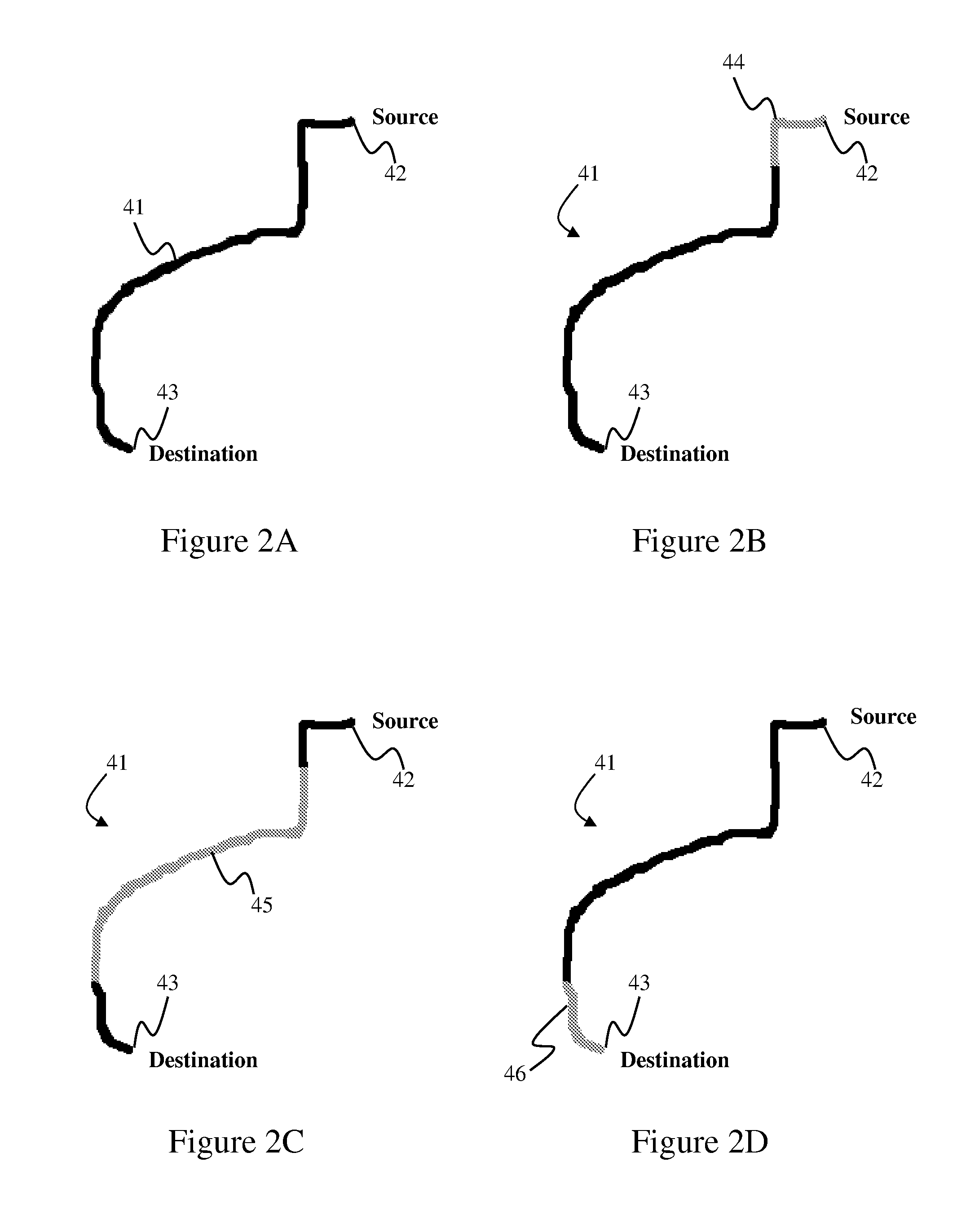
[0027]The present invention utilizes a geodatabase consisting of regular database tables and feature classes. Feature classes are tables that hold geographic shapes. The method requires a shortest path solver that determines the shortest path between two points in a street network.

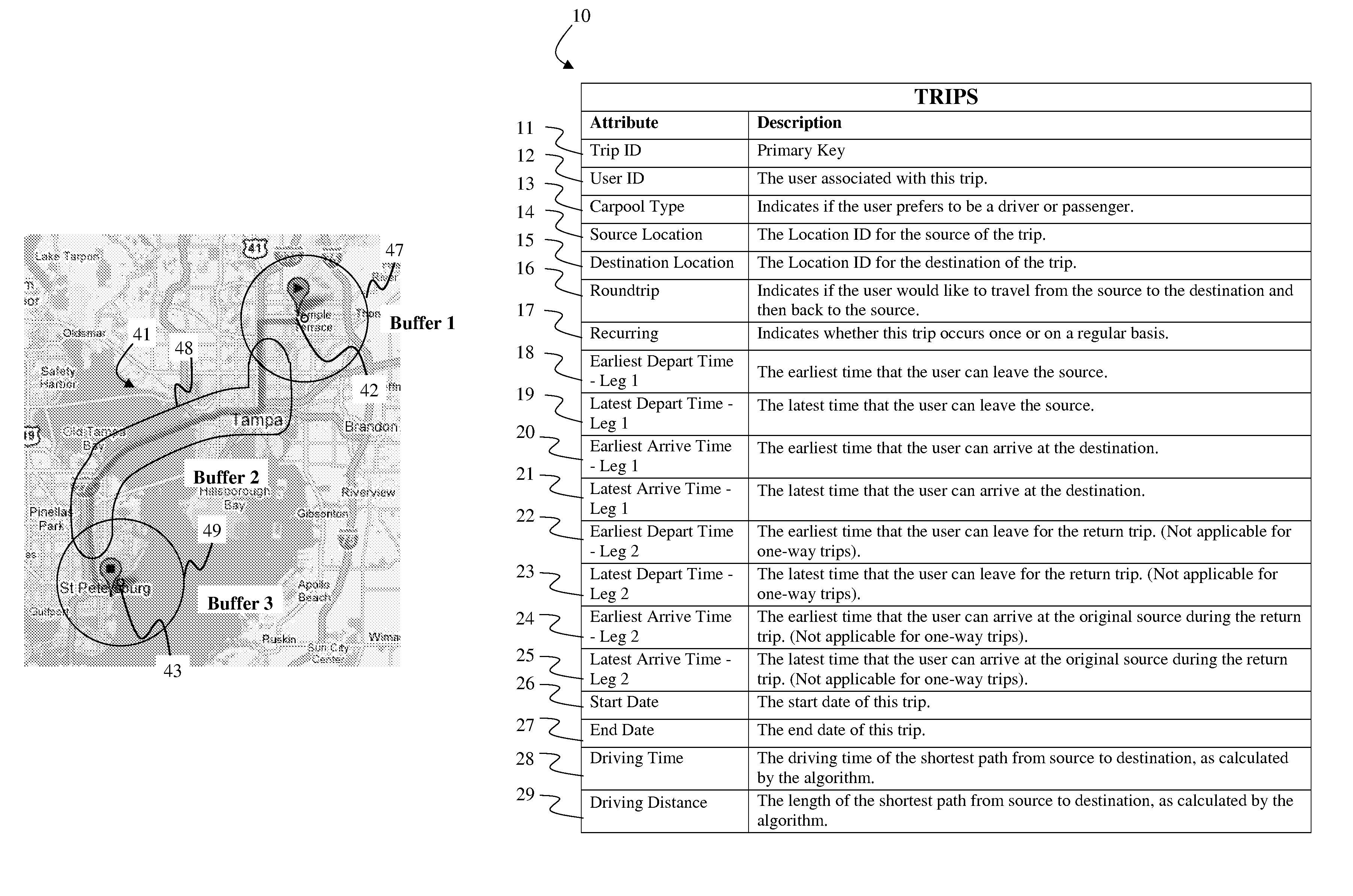
[0028]The inputs for the method include a series of tables that describe the user's trip and the trips previously input by other users. In practice, additional fields may be added to the tables to support the user interface. The tables include the Trips Table (FIG. 9), the Locations Table (FIG. 10), the Trip Schedules Table (FIG. 11), and the Matches Table (FIG. 16). The feature classes include the Points Feature Class (FIG. 12), the Shortest Path Feature Class (FIG. 13), and the Carpool Shortest Path Feature Class (FIG. 17).

[0029]Trips Module: In one embodiment, the invention stores a plurality of parameters relating to the trips to be taken by the users. In a preferred embodiment, these parameters are st...


PUM


Abstract

A ride matching method is disclosed herein. The ride matching method addresses many of the limitations associated with traditional dynamic ride matching applications. The method is unique in its ability to accept trips with schedules that cannot be expressed in terms of a simple recurrence pattern (e.g. Monday thru Friday work schedule). It can handle one-time and occasional trips. It is also distinct in its use of spatial analysis techniques to locate matches. Specifically, the use of a shortest path solver enables the ride matching method to perform a search along the path of a user's trip, in addition to the customary radial search around the endpoints. The shortest path solver is also used to calculate the driving distance between the user and a match. This provides a more accurate measurement than the straight-line distance used by other methods, especially in the presence of barriers.

Description


Claims


Application Information

Patent Timeline
Owner UNIV OF SOUTH FLORIDA
Why Eureka
Try Eureka