Utility light with articulating mounting legs adapted with suction cup fasteners

a technology of utility lights and mounting legs, which is applied in the field of mounting utility lights, can solve the problems of inability to show a portable, battery-powered i.e. cordless apparatus, inability to achieve widespread commercial success, and burdening background art references with limitations and disadvantages, etc., and achieves the effect of convenient use, quick and easy configuration

Inactive Publication Date: 2012-03-27
PEAK JASON
View PDF24 Cites 66 Cited by
  • Summary
  • Abstract
  • Description
  • Claims
  • Application Information

AI Technical Summary

Benefits of technology

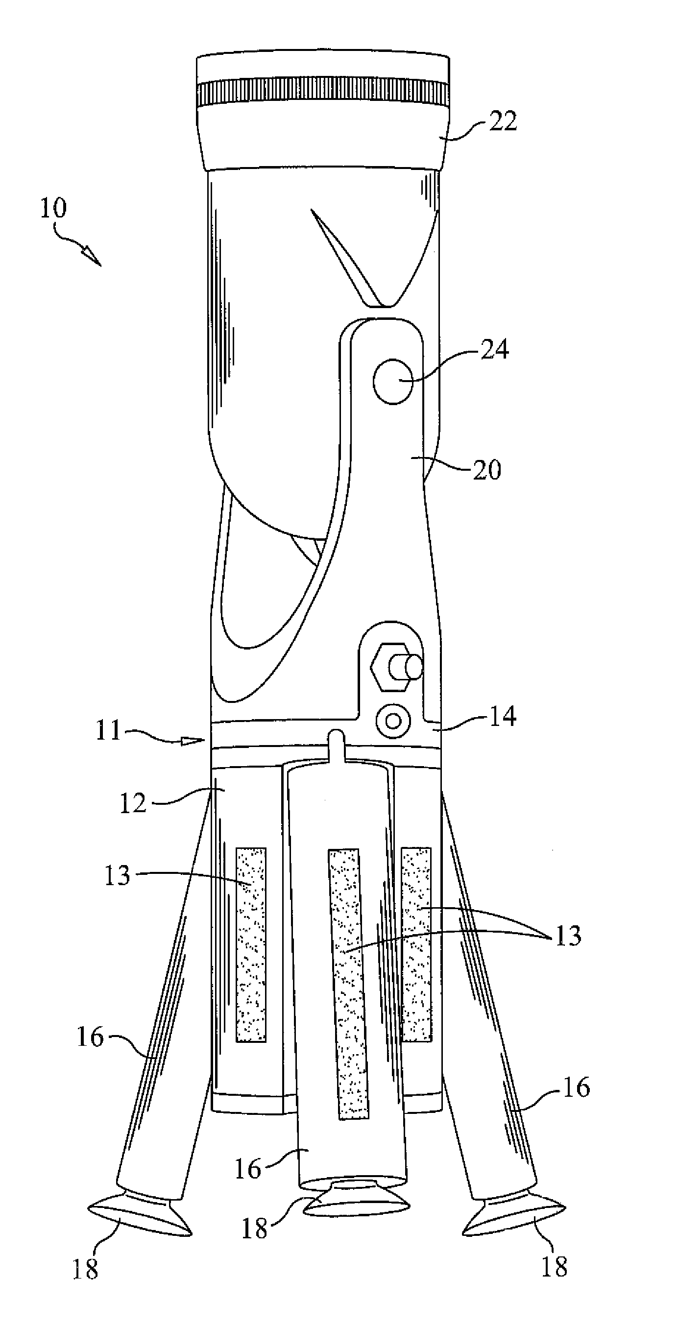
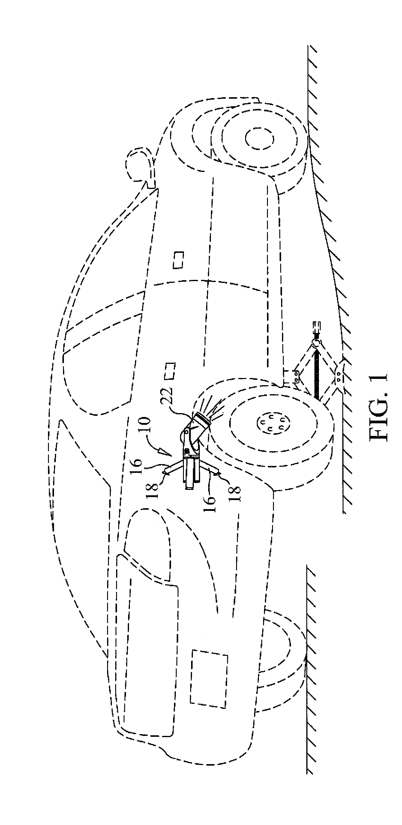
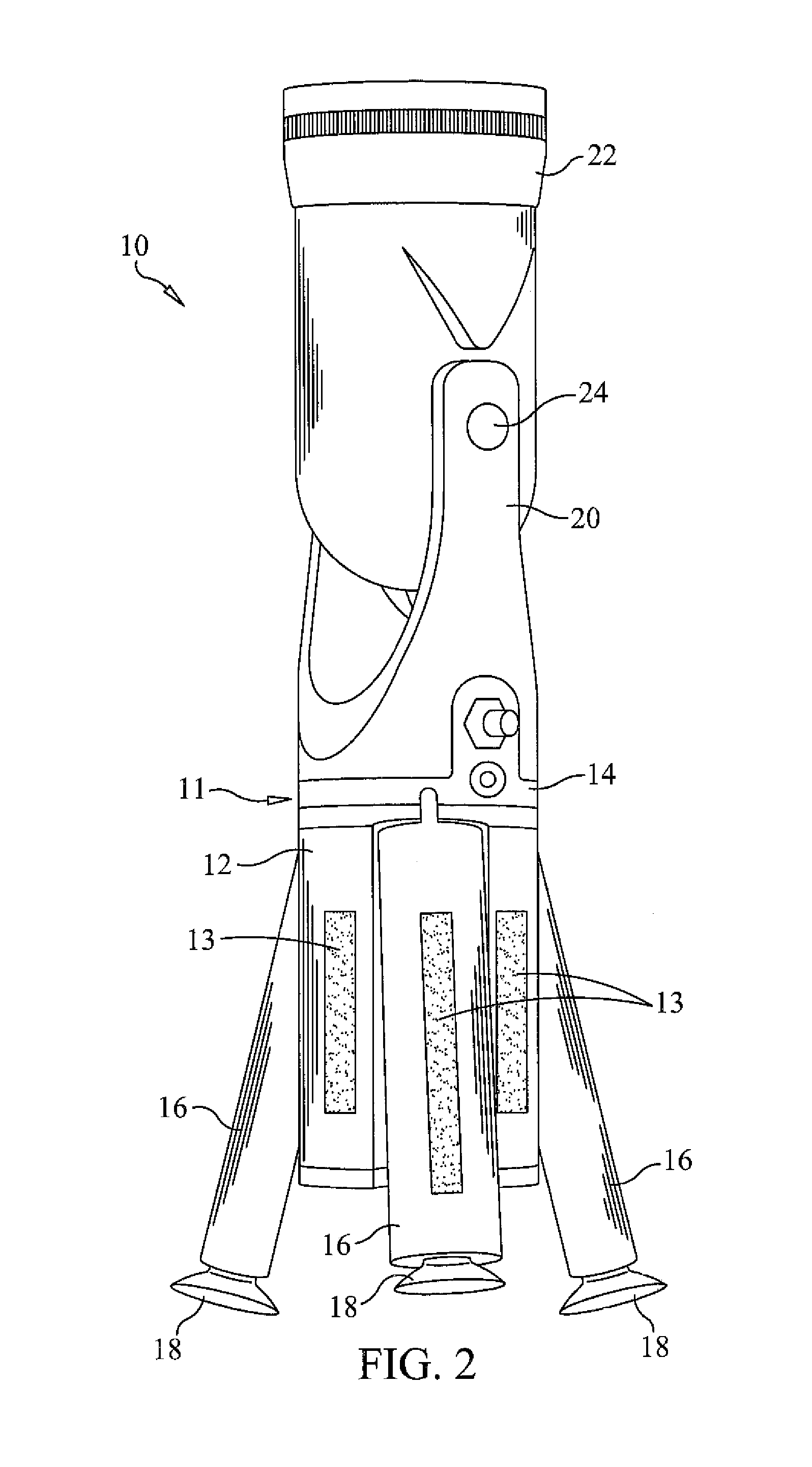
[0011]In a preferred embodiment, the main body comprises an elongate generally cylindrical structure wherein the first and second portions are connected and capable of rotation relative to one another about an elongate axis of the main body. In a preferred embodiment, the second end is connected to the first end by a swivel connection that allows relative rotation of approximately 270-degrees. The main body first end includes a battery compartment for housing a battery power source, and is further adapted with a plurality of circumferentially spaced articulating legs. Each articulating leg is configurable between a stowed configuration wherein the leg is substantially parallel with the longitudinal axis of the main body, and a deployed configuration wherein the leg is angularly disposed outward. Each leg includes a distal end having a suction cup, or other attachment structure (e.g. magnet), connected thereto for removable attachment to a smooth surface, such as the side of a vehicle. The combination of three deployable articulating legs terminating in suction cups, allows the main body to be easily configured for removable attachment to a vehicle side panel of virtually any shape or contour. The main body second end includes a light source pivotally connected thereto to allow for 270-degree pivotal positioning and adjustment thereof when in use. Reflective material may be affixed to the main body to reflect light from oncoming vehicles in roadside environments.
[0012]The present invention thus provides a utility light that may be quickly and easily put into use by positioning the legs such that the suction cups may be moved into engagement with a surface, such as a vehicle fender panel when changing a flat tire, so as to provide illumination to a desired area. In an alternate embodiment, one or more additional lighting units are provided for additional illumination.
[0013]Accordingly, it is an object of the present invention to provide an improved battery powered utility light.
[0015]Still another object of the present invention is to provide a utility light having a highly adaptable mounting structure to allow for custom configuration to enable removable attachment to vehicle panels of various shapes.

Problems solved by technology

Although an array of lighting sources are commercially available, prior art fails to show a portable, battery-powered i.e. cordless apparatus, which features LED lights on a swiveling mount, an adjustably articulating and telescoping tripod base, and suction attachment capabilities.
The references of the background art are burdened by a host of limitations and disadvantages and have otherwise failed to achieve widespread commercial success.

Method used


Image

  • Utility light with articulating mounting legs adapted with suction cup fasteners
  • Utility light with articulating mounting legs adapted with suction cup fasteners
  • Utility light with articulating mounting legs adapted with suction cup fasteners

Examples


Embodiment Construction

[0022]With reference now to the drawings, FIGS. 1-5 depict a portable, battery-powered utility light, generally referenced as 10, in accordance with the present invention. The present invention provides a portable utility light that is removably mountable to a surface, such as the side of an automobile, for providing temporary emergency lighting as illustrated in FIG. 1. A utility light in accordance with the present invention is particularly useful by motorists tasked with having to change a flat tire in any low-light condition.

[0023]Utility light 10 includes a main body, generally referenced as 11, which comprises an elongate generally cylindrical structure generally including a first end portion 12 and a second end portion 14. The first and second end portions, referenced as 12 and 14 respectively, are adapted to a swivel relative to one another, preferably having a high-degree of freedom of swiveling movement. In a preferred embodiment, the first and second end portions are capa...


PUM


Abstract

A portable utility light is provided for removable mounting to a surface, such as the side of an automobile, for providing temporary emergency lighting. The utility light includes a main body having first end portion adapted with mounting structure to facilitate removable attachment to a smooth surface, and a second end portion adapted with light emitting device, such as one or more light emitting diodes (“LED's”). The main body comprises an elongate generally cylindrical structure wherein the first and second portions are connected and capable of rotation relative to one another about an elongate axis. The main body first end includes a battery compartment for housing a battery power source, and is further adapted with a plurality of circumferentially spaced articulating legs.

Description

CROSS REFERENCE TO RELATED APPLICATIONS[0001]This application claims the benefit of provisional U.S. Patent Application Ser. No. 61 / 175,192, filed on May 4, 2009.STATEMENT REGARDING FEDERALLY SPONSORED RESEARCH OR DEVELOPMENT[0002]N / ACOPYRIGHT NOTICE[0003]A portion of the disclosure of this patent document contains material that is subject to copyright protection. The copyright owner has no objection to the facsimile reproduction by anyone of the patent document or patent disclosure as it appears in the Patent and Trademark Office patent file or records, but otherwise reserves all copyrights rights whatsoever.BACKGROUND OF THE INVENTION[0004]1. Field of the Invention[0005]The present invention relates generally to mountable utility lights, and more particularly to a utility light apparatus having a mounting base with a plurality of adjustable articulating legs adapted with suction cup fasteners for removable attachment to a surface.[0006]2. Description of Related Art[0007]Portable l...

Claims


Application Information

Patent Timeline
Patent Type & Authority Patents(United States)
IPC IPC(8): F21L4/00
CPCF21V21/06F21V21/0925F21L4/08B60Q1/2615B60Q1/52B60Q1/247B60Q7/00
Inventor PEAK, JASON
Owner PEAK JASON
Why Eureka
Try Eureka