
Arrangement and device for using a template to form holes for implants in bone, preferably jaw bone

a template and bone technology, applied in the field of bone implant hole arrangement, can solve the problems of inconvenient patient care, large disadvantage in exposing the jaw bone surgical intervention, and difficulty in obtaining the necessarily exact hole formation, so as to avoid impingement on the nerve path

Inactive Publication Date: 2012-03-27
NOBEL BIOCARE SERVICES AG
View PDF120 Cites 50 Cited by
  • Summary
  • Abstract
  • Description
  • Claims
  • Application Information

AI Technical Summary

Problems solved by technology

It is also known that it can be difficult to obtain the necessarily exact hole formation unless the gum, i.e. the gingiva, is folded back and the jaw bone thereby exposed, because the gum resilient properties can interfere with the template application and the hole formation.
There is a great disadvantage in carrying out surgical interventions for exposing the jaw bone, i.e. by folding back the gum.
This causes inconveniences for the patient, and the implantation work is also painful because the formation of the hole and insertion of the implant have to be followed by a process of healing, which can last some considerable time.

Method used


Image

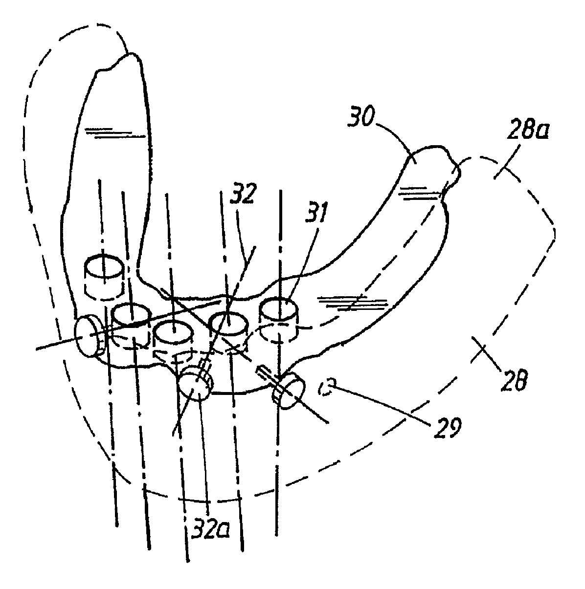
  • Arrangement and device for using a template to form holes for implants in bone, preferably jaw bone
  • Arrangement and device for using a template to form holes for implants in bone, preferably jaw bone
  • Arrangement and device for using a template to form holes for implants in bone, preferably jaw bone

Examples


Embodiment Construction

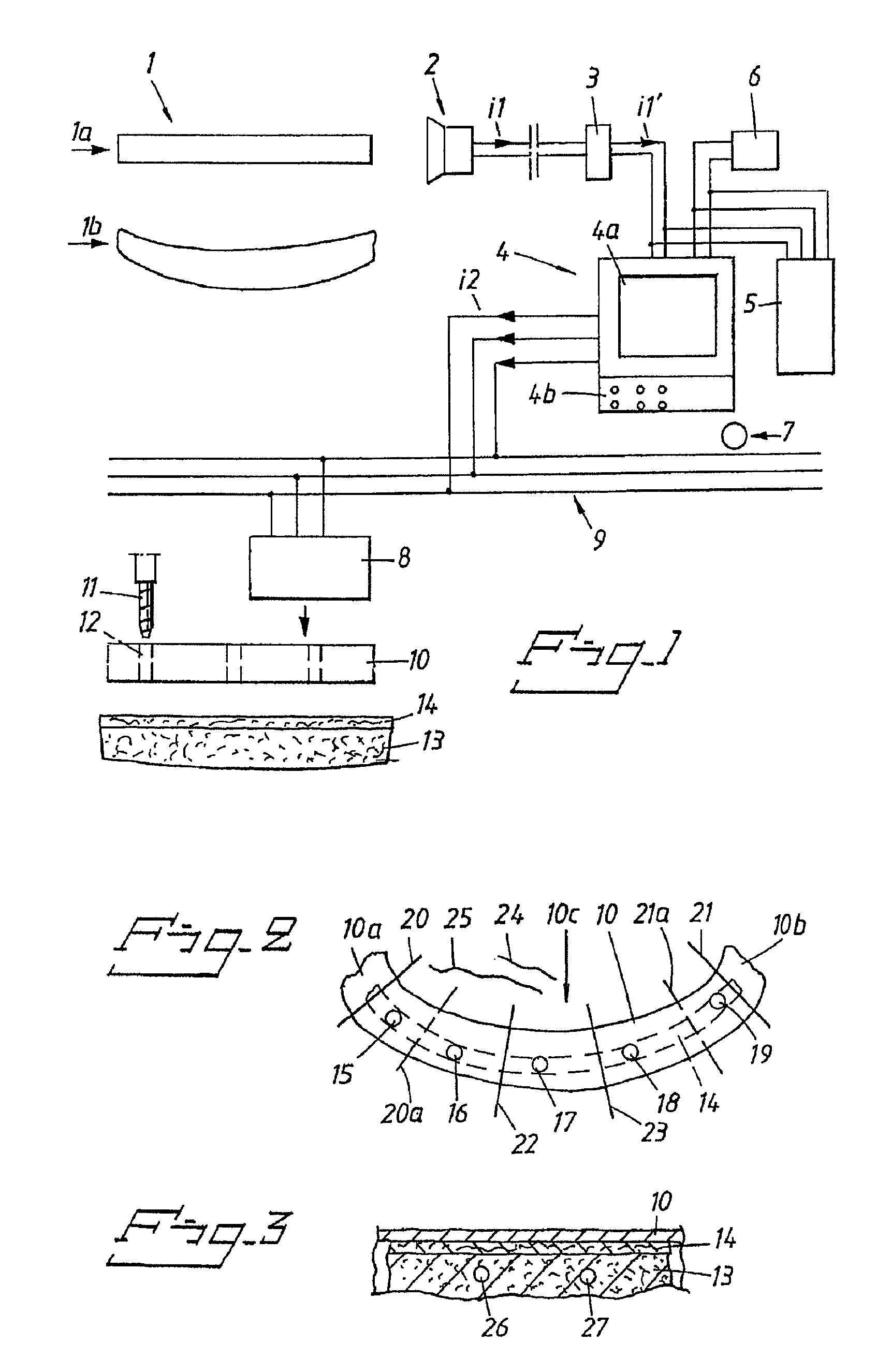
[0021]In FIG. 1, an implant site in the form of or on a jaw bone is indicated diagrammatically by 1. The jaw bone is shown in a vertical view 1a, and in a horizontal view 1b. In this exemplary embodiment, the implant site or the jaw bone is to be provided with a dental bridge and in this example, all the teeth in the jaw bone in question are to be replaced by a dental bridge. The implant can be scanned with a scanning function, which can be an X-ray function, or computed tomography.

[0022]Alternatively, the scanning of the implant site can be done in an alternative way by conventional scanning, e.g., by a camera, etc. The scanning function in question is indicated diagrammatically by 2, and the scanning function or the scanning equipment is arranged to generate scanning dependent signals in a conventional manner. The equipment comprises an apparatus 3 receiving the signals i1. This apparatus 3 is arranged to generate signals i1′, as a function of the signals i1, and send them to a co...


PUM


Abstract

An apparatus includes a template which locates hole positions in a jawbone while the template is separated from the jawbone by gum tissue. The template follows a contour of the gum tissue surrounding the jawbone and has guide holes which receive a cutting tool. Anchoring elements attach the template to the jawbone. A system includes means for scanning an implantation site on a patient's jawbone, simulating the implantation site, and determining nerve-rich areas or nerve paths in the jawbone. A holed template is produced which is separated from the jawbone by at least gum tissue of the patient. Attachment hole positions in the jawbone are located so as to avoid nerve paths. A method of forming holes to attach a dental implant to a patient's jaw bone without surgical intervention in gum tissue of the patient to expose the jawbone is disclosed which avoids impingement on a nerve path.

Description

CROSS-REFERENCE TO RELATED APPLICATIONS[0001]This Application is a continuation of U.S. patent application Ser. No. 10 / 710,170, now issued as U.S. Pat. No. 7,950,924, filed Jun. 23, 2004, which is a continuation of International Application No. PCT / SE02 / 02393, with an international filing date of Dec. 19, 2002, which claims priority under 35 U.S.C. §119 to Swedish Patent Application No. SE 0104431-2, filed on Dec. 28, 2001 in Sweden. The entire contents of each of the foregoing applications are incorporated herein by reference.BACKGROUND OF THE INVENTION[0002]This disclosure relates in various aspects to an arrangement for using a template to form holes for implants in bone, preferably jaw bone, without any negative effect from the existing resiliency in the flesh surrounding the bone, for example the gum (gingiva). The template in question may be adapted to the shape or shapes of the bone and of the gum and has guide holes for a hole-forming unit which can consist of conventional d...

Claims


Application Information

Patent Timeline
Patent Type & Authority Patents(United States)
IPC IPC(8): A61C3/00A61B17/17A61B19/00A61C1/08A61C13/00
CPCA61B17/176A61C1/084A61C13/0004A61B19/50A61B34/10
Inventor BRAJNOVIC, IZIDOR
Owner NOBEL BIOCARE SERVICES AG
Learn More