
Attachment members with internally located radiopaque information markers for ct scan

a technology of internal location and radiopaque information, applied in the field of ct scanning attachment members, can solve the problems of occlusal surface, affecting the accuracy of future scans of pre-defined scan members, and altering scannable features

Active Publication Date: 2017-04-27
BIOMET 3I LLC
View PDF10 Cites 29 Cited by
  • Summary
  • Abstract
  • Description
  • Claims
  • Application Information

AI Technical Summary

Benefits of technology

The present patent is about attachment members that are used to attach dental implants to a patient's mouth. These attachment members have different features than previous scan members in that they have non-visible radiopaque information markers that are only revealed through a computerized tomography (CT) scan. These attachment members can be customized based on the dental implant and the patient's needs. The CT scan data is used to create a three-dimensional model of the mouth, which can be used to design and manufacture custom abutments or permanent prosthesis for the dental implant. The technical effect of this patent is that it provides a more accurate and efficient way to attach dental implants to a patient's mouth.

Problems solved by technology

However, these prior pre-defined scan members only include the visually scannable features on an exposed top occlusal surface of the scan members.
Thus, the exposed top occlusal surface may have geometric limitations such that the exposed top occlusal surface was suitable for including the visually scannable features in a manner that readily allowed the visually scannable features to be picked-up in a scan and interpreted.
And some pre-defined scan members may be installed in a patient's mouth during the healing period (e.g., for several months) such that the pre-defined scan members (especially their exposed occlusal surface that includes the scannable features) are subjected to wear and tear due to standard mastication, which could alter the scannable features and impact accuracy of future scans of the pre-defined scan members.

Method used


Image

  • Attachment members with internally located radiopaque information markers for ct scan
  • Attachment members with internally located radiopaque information markers for ct scan
  • Attachment members with internally located radiopaque information markers for ct scan

Examples


Embodiment Construction

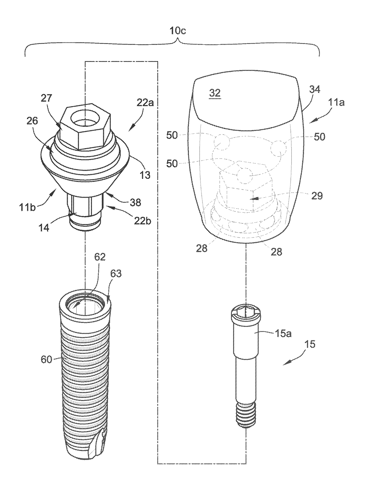
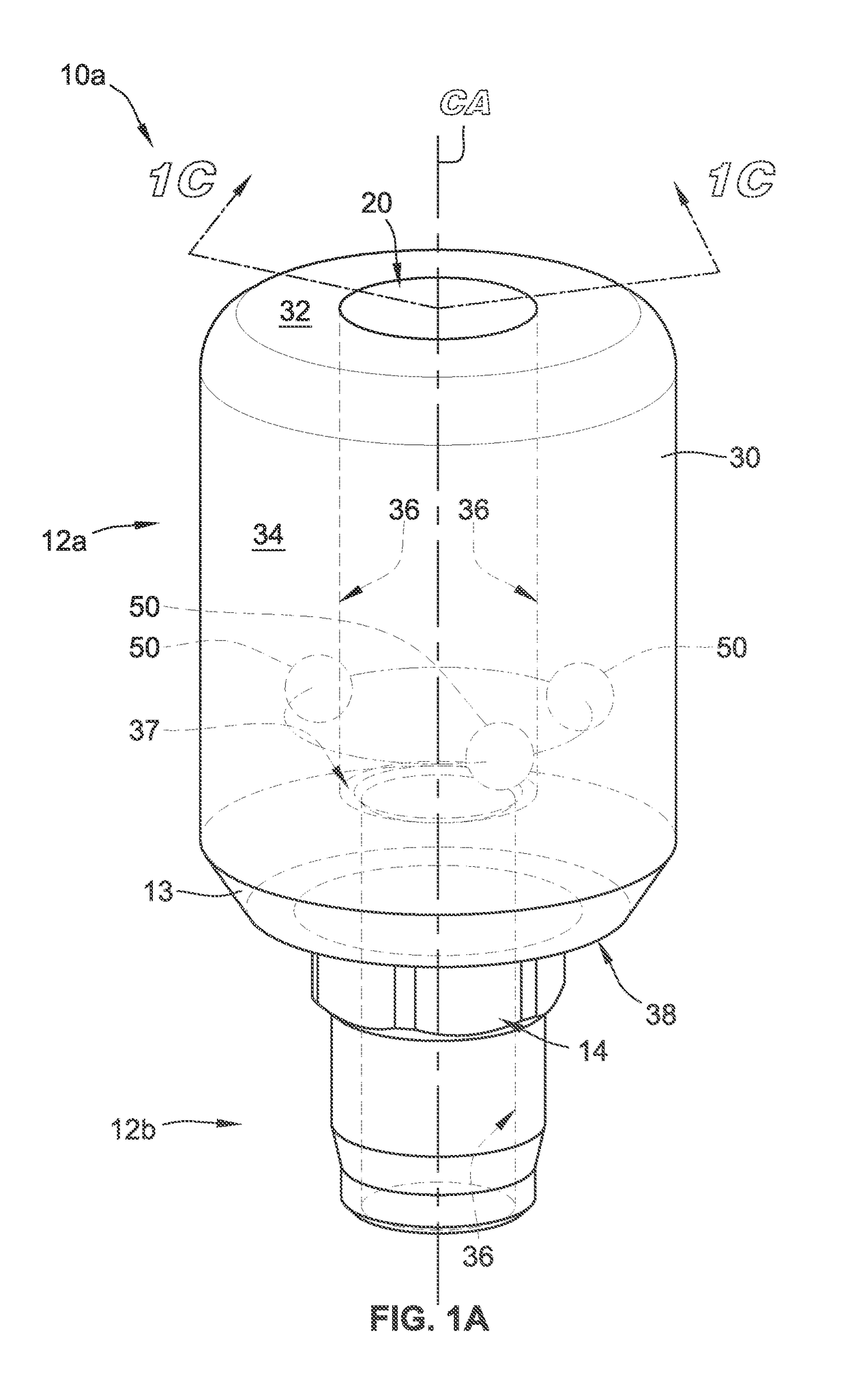
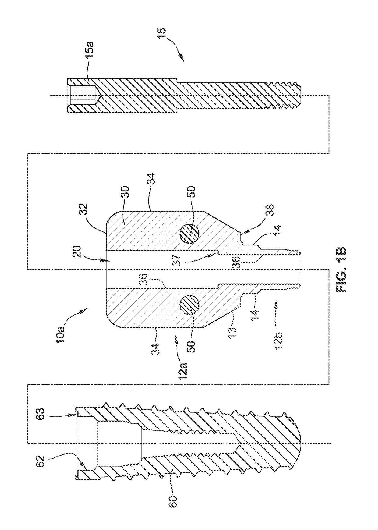
[0036]Referring to FIGS. 1A-1C, an attachment member 10a is illustrated that is used to develop final or permanent patient-specific prostheses in accordance with the present disclosure. Further, the attachment member 10a can serve as a gingival healing abutment. The attachment member 10a has an upper or supragingival region 12a and a lower or subgingival region 12b, which are separated by a transition section 13, although the transition section 13 may be integral and included with the supragingival region 12a or the subgingival region 12b. Any portion of the transition section 13 and / or of the supragingival region 12a can be placed subgingival (e.g., below the gingival tissue) for a given installation. Similarly, any portion of the transition section 13 and / or of the subgingival region 12b can be placed supragingival (e.g., above the gingival tissue) for a given installation. Moreover, the supragingival region 12a can be referred to as a post region that is partially subgingival and...


PUM


Abstract

An attachment member for mating with a dental implant includes a non-rotational structure and a body. The non-rotational structure is configured to mate with a corresponding non-rotational feature of the dental implant. The body extends from the non-rotational structure. The body has (i) an exterior side surface configured to at least partially engage gingival tissue adjacent to the dental implant, (ii) an exterior top surface that is exposed through the gingival tissue, (iii) a screw access bore for receiving a screw that attaches the attachment member to the dental implant in a removable fashion, and (iv) a set of radiopaque information markers that is located internal to the exterior side surface and the exterior top surface. The set of radiopaque information markers indicates information regarding the dental implant that is revealed in response to a scan from a computerized tomography (CT) scanner.

Description

CLAIM OF PRIORITY[0001]This application claims the benefit of U.S. Provisional Patent Application Ser. No. 62 / 244,548, filed on Oct. 21, 2015, the benefit of priority of which is claimed hereby, and which is incorporated by reference herein in its entirety.FIELD OF THE INVENTION[0002]The present disclosure relates generally to attachment members with internally located radiopaque information markers. More particularly, the present disclosure relates to CT scanning attachment members with internally located radiopaque information markers for use in developing a final dental prosthesis.BACKGROUND OF THE INVENTION[0003]The dental restoration of a partially or wholly edentulous patient with artificial dentition is typically done in two stages. In the first stage, an incision is made through the gingiva to expose the underlying bone. An artificial tooth root, in the form of a dental implant, is placed in the jawbone for osseointegration. The dental implant generally includes a threaded b...

Claims


Application Information

Patent Timeline
Patent Type & Authority Applications(United States)
IPC IPC(8): A61C8/00A61C13/34A61C13/00A61B6/03A61B6/14A61B6/51
CPCA61C8/0001A61B6/032A61B6/14A61B2090/3966A61C13/0004A61C13/34A61B2090/3916A61C8/006A61C8/005A61C8/0068A61C2201/005A61C8/008A61C9/004A61B6/51
Inventor SUTTIN, ZACHARY B.PORTER, STEPHEN S.
Owner BIOMET 3I LLC
Learn More