Multichannel contactless power transfer system for a computed tomography system

a power transfer system and computed tomography technology, applied in the field of multichannel contactless power transfer systems for computed tomography systems, can solve the problems of brush and slip ring mechanisms, maintenance problems, and increased weight, volume and complexity of the system,

Active Publication Date: 2006-05-30
GENERAL ELECTRIC CO
View PDF12 Cites 90 Cited by
  • Summary
  • Abstract
  • Description
  • Claims
  • Application Information

AI Technical Summary

Problems solved by technology

Unfortunately, placing the inverter on the rotational gantry increases the weight, volume and complexity of the system.
Furthermore, brush and slip ring mechanisms (which are typically used to carry appreciable current) are subject to reduced reliability, maintenance problems, and electrical noise generation, which interferes with sensitive modern medical diagnostic procedures, especially in harsh environments.

Method used


Image

  • Multichannel contactless power transfer system for a computed tomography system
  • Multichannel contactless power transfer system for a computed tomography system
  • Multichannel contactless power transfer system for a computed tomography system

Examples


Embodiment Construction

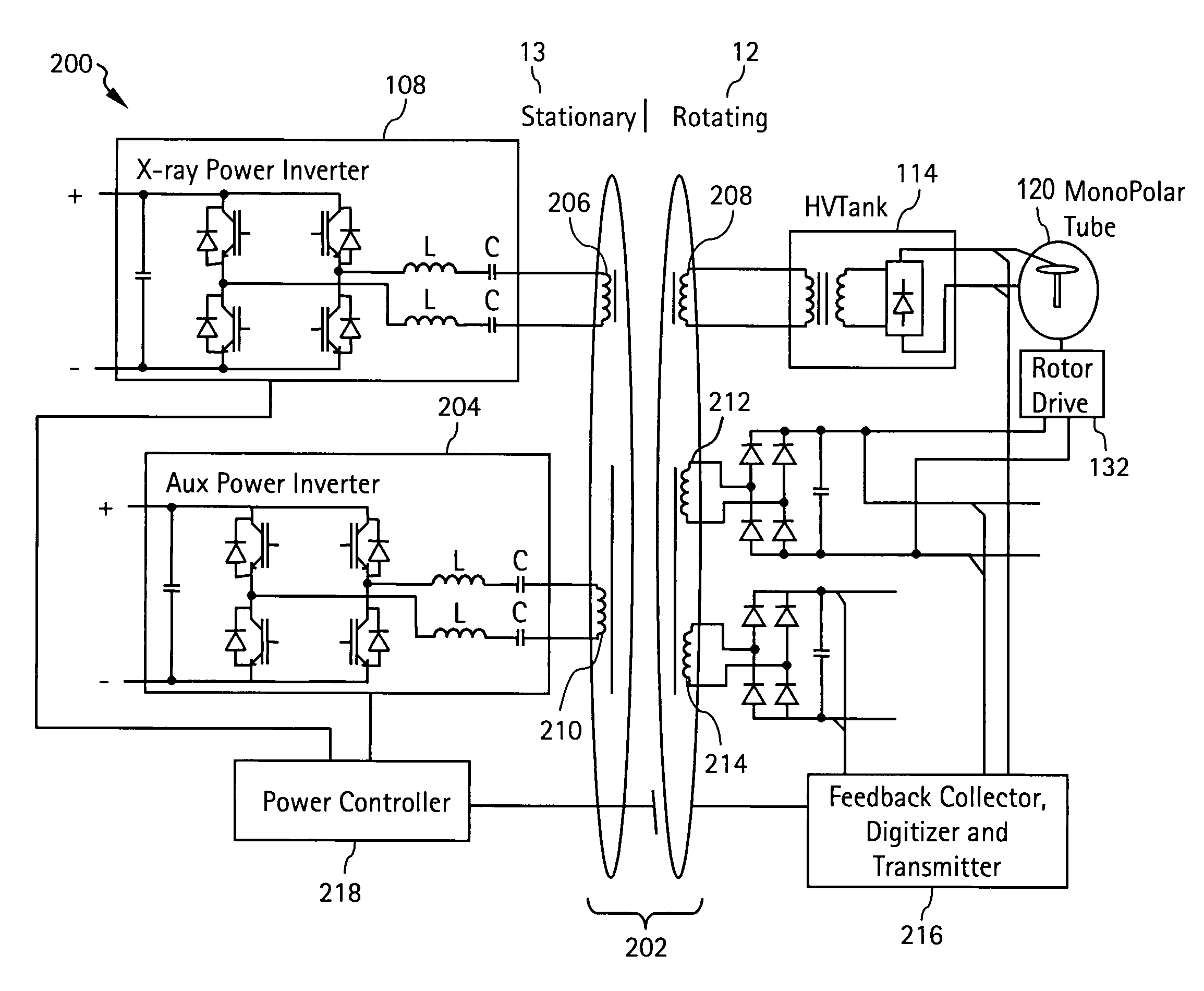
[0017]Disclosed herein is a multichannel, contactless power transfer system for a CT system that provides both X-ray generator and auxiliary power to the rotating portion of the CT system through the use of a multiple channel rotary transformer. Thus, the non-contacting manner in which power is transferred (i.e., through electromagnetic induction) is used for all of the CT system power transfer needs. Thereby, the CT system is characterized by a reduced complexity, in that a greater number of components may be removed from the rotating side of the gantry. In addition, the present invention embodiments further address radiated EM noise and other details of the rotary transformer windings for adapting a multichannel, contactless power transfer system to a CT system.

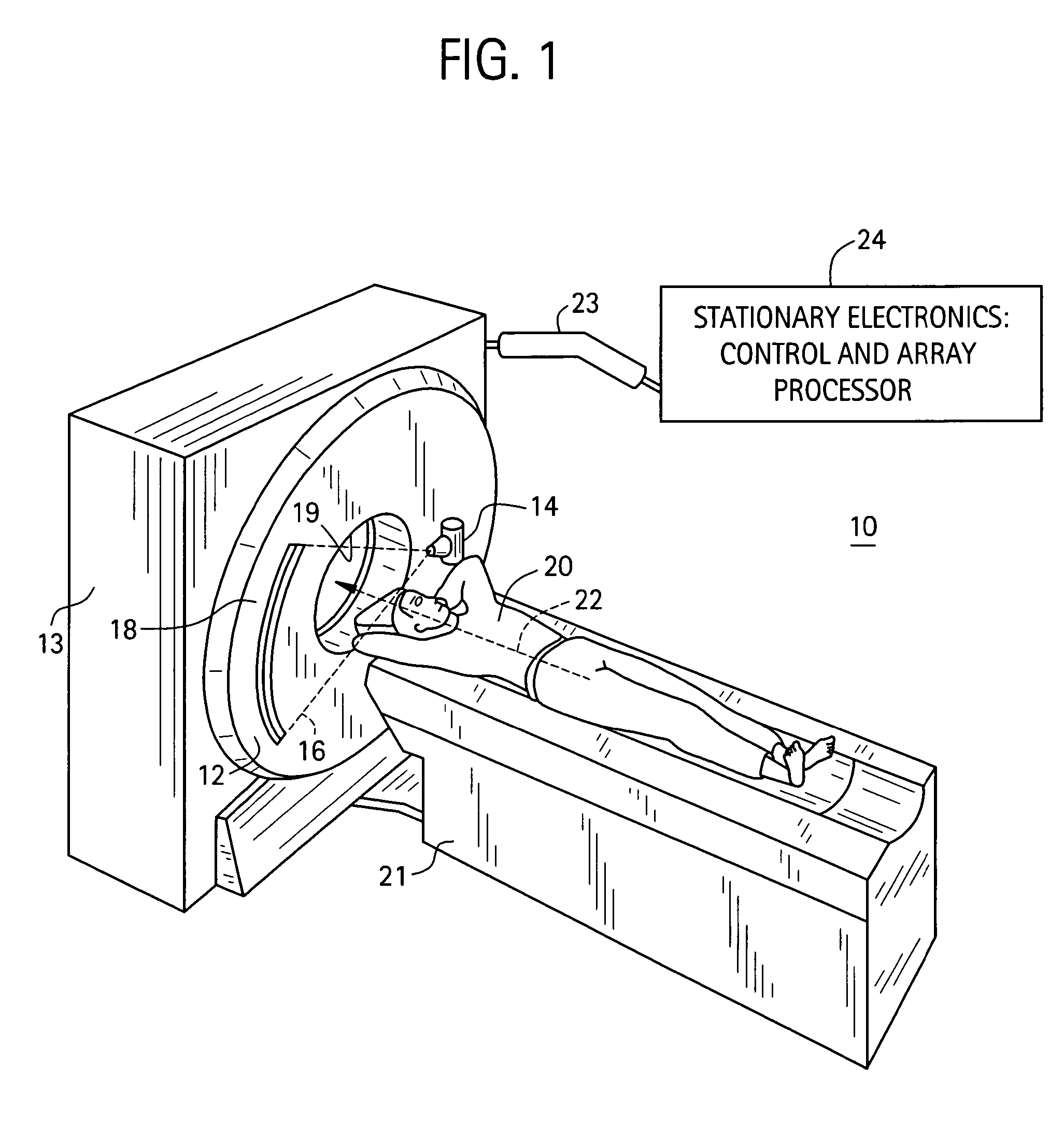
[0018]Referring initially to FIG. 1, there is shown an exemplary computerized tomography (CT) system 10 suitable for use in accordance with an embodiment of the invention. The system 10 includes a generally annular rotating...


PUM

PropertyMeasurementUnit
power capabilityaaaaaaaaaa
DC voltagesaaaaaaaaaa

Abstract

A multichannel, contactless power transfer system includes a primary power inverter disposed on a stationary side of the system, and an auxiliary power inverter disposed on the stationary side of the system. A rotary transformer has a primary side thereof disposed on the stationary side of the system and a secondary side disposed on a rotating side of the system. The rotary transformer is configured to couple primary power from an output of the primary power inverter to a primary power voltage output on the rotating side of the system, and is further configured to couple auxiliary power from an output of the auxiliary power inverter to at least one auxiliary voltage output on the rotating side of the system.

Description

BACKGROUND OF THE INVENTION[0001]The present disclosure relates generally to power transfer mechanisms and, more particularly, to a multichannel, contactless power transfer system for a computed tomography (CT) system.[0002]Computed tomography (CT) systems are used to obtain non-invasive sectional images of test objects, particularly internal images of human tissue for medical analysis and treatment. Current CT systems position the test object, such as a patient, on a table within a central aperture of a rotating frame, or gantry, which is supported by a stationary frame. The gantry includes an x-ray source and a detector array positioned on opposite sides of the aperture, within an x-y plane of a Cartesian coordinate system (generally referred to as the “imaging plane”), such that both rotate with the gantry around the test object being imaged. At each of several angular positions along the rotational path of the gantry (also referred to as “projections”), the x-ray source emits a ...

Claims


Application Information

Patent Timeline
Patent Type & Authority Patents(United States)
IPC IPC(8): H05G1/10A61B6/00G01N23/00G21K1/12H05G1/60
CPCH05G1/10A61B6/56
Inventor KATCHA, JASON STUARTSCHMIDT, JONATHAN RICHARDGONZALEZ, MARCELAPEARSON, JR., PHIL E.
Owner GENERAL ELECTRIC CO
Why Eureka
Try Eureka