Computed tomography system for imaging of human and small animal

a computed tomography and human-sized animal technology, applied in tomography, material analysis using wave/particle radiation, instruments, etc., can solve the problems of reducing the imaging speed, reducing the spatial resolution in the illumination direction, and occupying a significantly larger spa

Inactive Publication Date: 2006-07-25
THE UNIV OF NORTH CAROLINA AT CHAPEL HILL
View PDF53 Cites 91 Cited by
  • Summary
  • Abstract
  • Description
  • Claims
  • Application Information

AI Technical Summary

Problems solved by technology

As a result, the spatial resolution in the illumination direction is lost.
Rotation of the x-ray source puts considerable demand on the system design and can reduce the imaging speed.
However, the machine is expensive and takes significantly larger space than a regular computed tomography system.

Method used


Image

  • Computed tomography system for imaging of human and small animal
  • Computed tomography system for imaging of human and small animal
  • Computed tomography system for imaging of human and small animal

Examples


Embodiment Construction

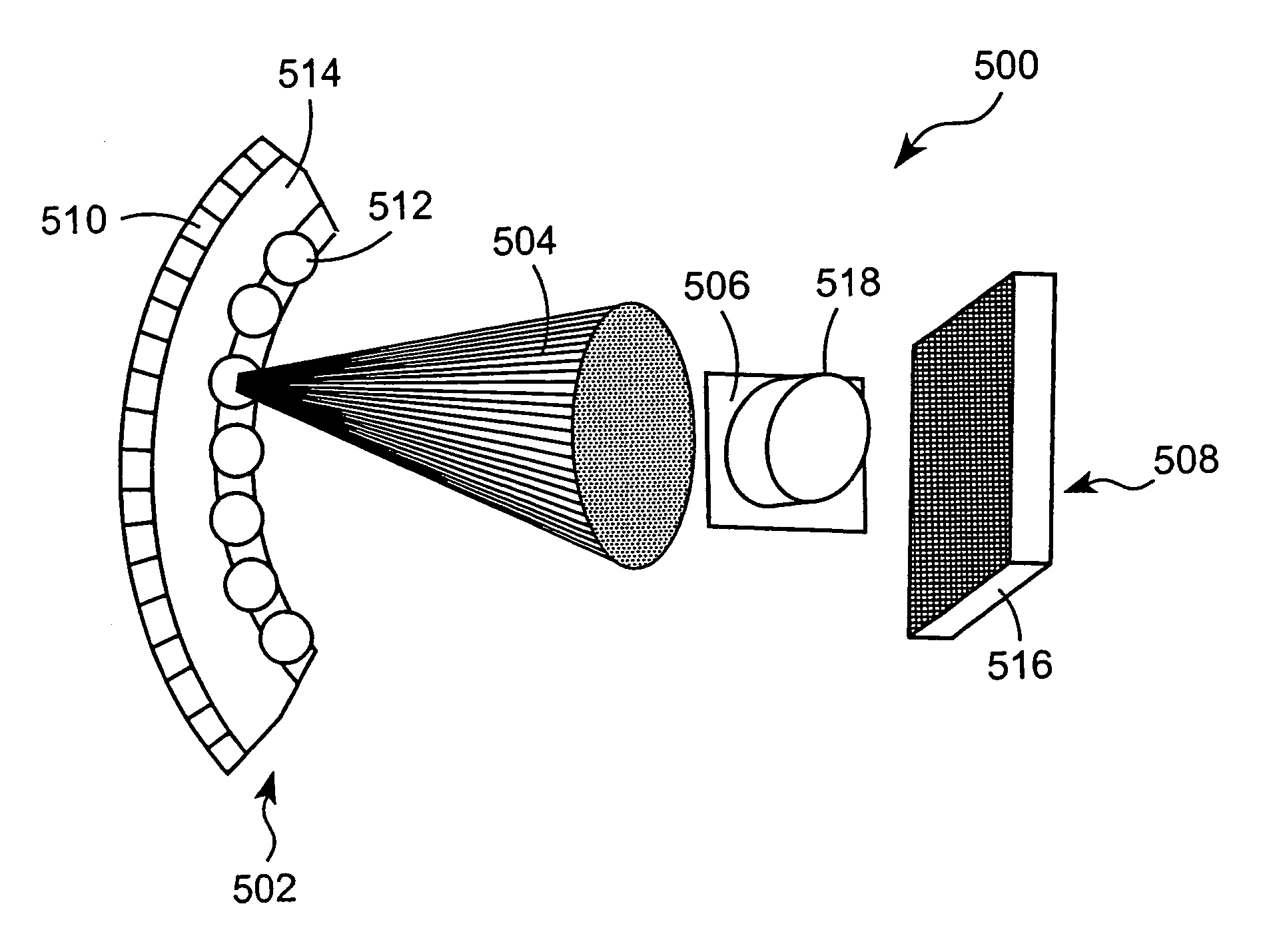
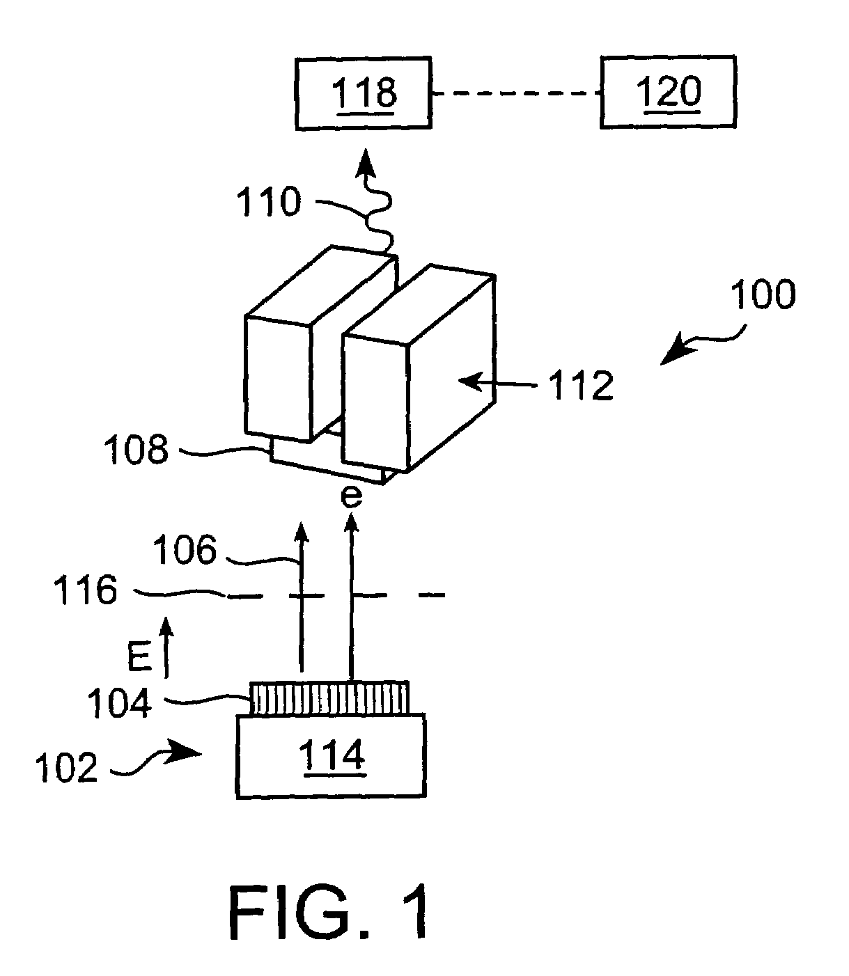
[0025]The x-ray systems and x-ray imaging methodologies for computed tomography disclosed herein are based on our previous disclosures, including U.S. patent application Ser. No. 09 / 679,303 entitled “X-RAY GENERATING MECHANISM USING ELECTRON FIELD EMISSION CATHODE”, U.S. patent application Ser. No. 10 / 051,183 entitled “LARGE-AREA INDIVIDUALLY ADDRESSABLE MULTI-BEAM X-RAY SYSTEM AND METHOD OF FORMING SAME”, and U.S. patent application Ser. No. 10 / 309,126 entitled “X-RAY GENERATING MECHANISM USING ELECTRON FIELD EMISSION CATHODE”, the entire disclosures of all these applications are herein incorporated by reference. U.S. patent application Ser. No. 09 / 679,303 discloses an x-ray generating device incorporating a nanostructure-containing material. U.S. patent application Ser. No. 10 / 051,183 discloses a structure to generate x-rays having a plurality of stationary and individually electrically addressable field emissive electron sources with a substrate composed of a field emissive mater...


PUM

PropertyMeasurementUnit
angleaaaaaaaaaa
angleaaaaaaaaaa
on-off frequencyaaaaaaaaaa

Abstract

Computed tomography device comprising an x-ray source and an x-ray detecting unit. The x-ray source comprises a cathode with a plurality of individually programmable electron emitting units that each emit an electron upon an application of an electric field, an anode target that emits an x-ray upon impact by the emitted electron, and a collimator. Each electron emitting unit includes an electron field emitting material. The electron field emitting material includes a nanostructured material or a plurality of nanotubes or a plurality of nanowires. Computed tomography methods are also provided.

Description

RELATED APPLICATIONS[0001]This application is a continuation-in-part of U.S. patent application Ser. No. 10 / 051,183 filed Jan. 22, 2002, now U.S. Pat. No. 6,876,724, which is a continuation-in-part of U.S. patent application Ser. No. 09 / 679,303 filed Oct. 6, 2000, now U.S. Pat. No. 6,553,096 issued Apr. 22, 2003. This application is also a continuation of U.S. patent application Ser. No. 10 / 421,931 filed Apr. 24, 2003, now abandoned. The contents of all of the above-cited applications being incorporated here by reference.STATEMENT REGARDING FEDERALLY SPONSORED RESEARCH OR DEVELOPMENT[0002]At least some aspects of this invention were made with Government support under the sponsorship of the Office of Naval Research, Contract No. N00014-98-1-0597. The Government may have certain rights in this invention.BACKGROUND[0003]1. Field of the Invention[0004]The present invention relates generally to field emission cathodes for x-ray radiation sources. More particularly, the present invention ...

Claims


Application Information

Patent Timeline
Patent Type & Authority Patents(United States)
IPC IPC(8): G01N23/00
CPCA61B6/032A61B6/4028B82Y10/00G01N23/046H01J35/065A61B6/508A61B6/541G01N2223/612H01J2201/30469H01J2235/068G01N2223/419G01N2223/316
Inventor ZHOU, OTTO Z.LU, JIANPINGLEE, YUEHLIN, WEILICHENG, YUANZHANG, JIAN
Owner THE UNIV OF NORTH CAROLINA AT CHAPEL HILL
Why Eureka
Try Eureka