
Brush section for an electric toothbrush

a toothbrush and electric technology, applied in the field of toothbrush sections for electric toothbrushes, can solve the problems of inadequate supply, inability to provide brush patterns, and require a relatively complex drive mechanism for separate motion, and achieve the effect of improving cleaning

Inactive Publication Date: 2005-02-01
COLGATE PALMOLIVE CO
View PDF3 Cites 23 Cited by
  • Summary
  • Abstract
  • Description
  • Claims
  • Application Information

AI Technical Summary

Benefits of technology

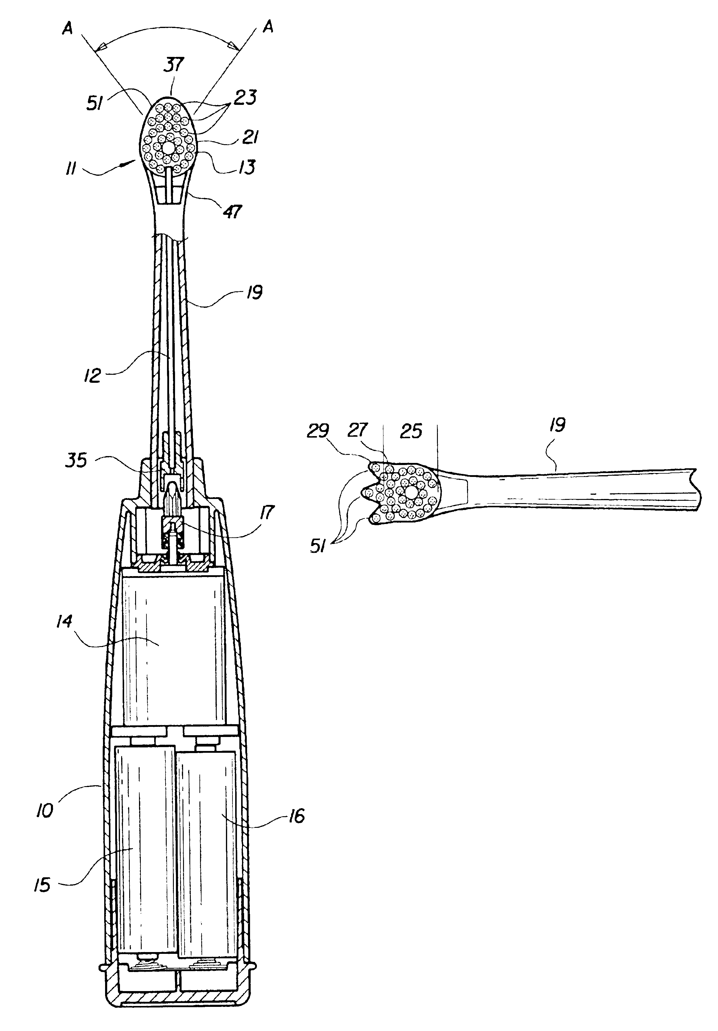
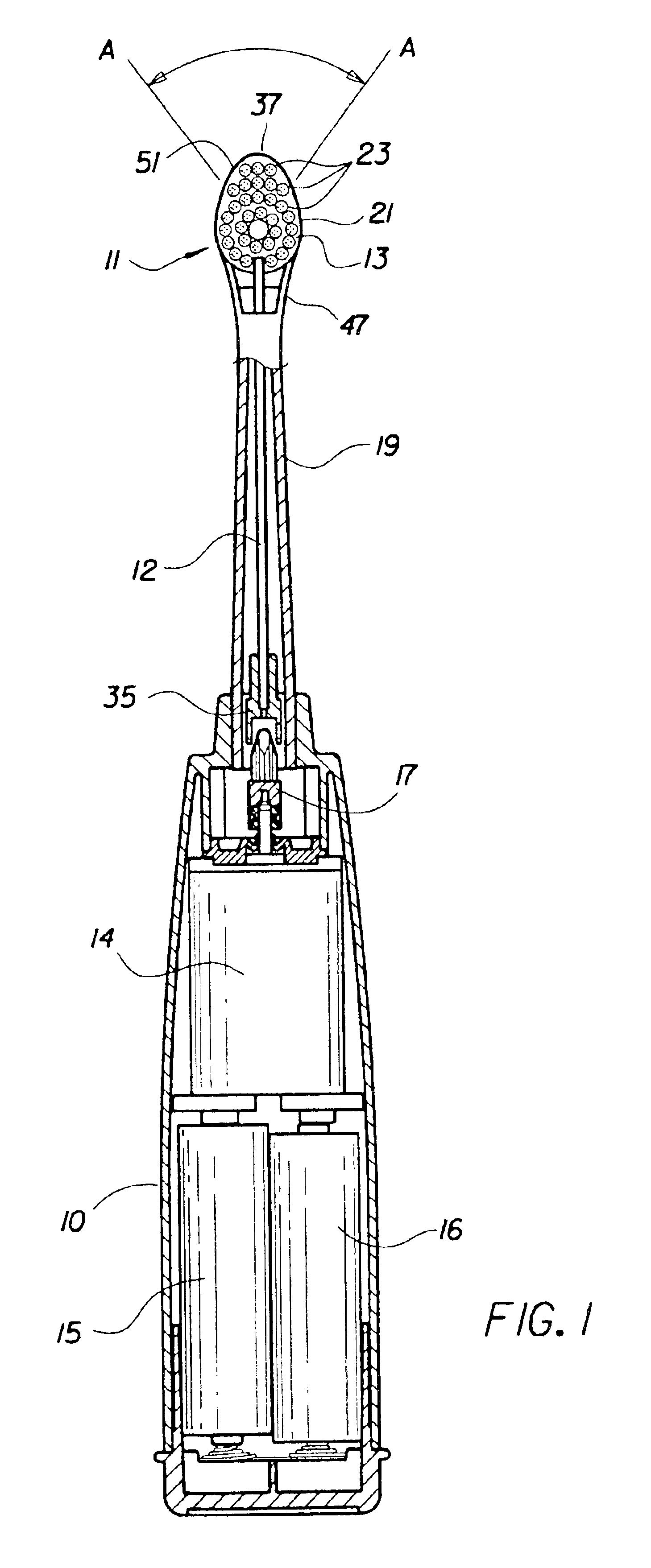
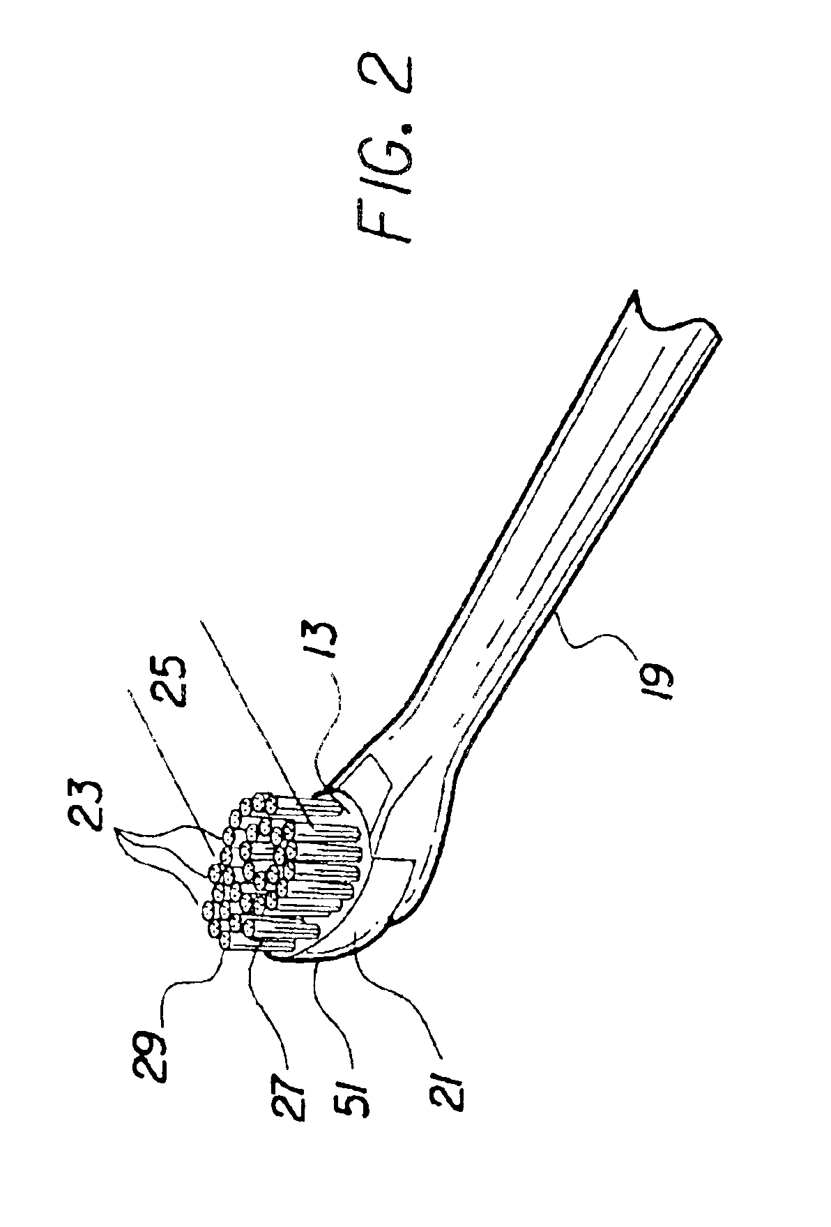
The present invention provides a brush section for an electric toothbrush and a method for use thereof, which brush section has at a first end a connector adapted to be joined to an electric toothbrush handle section and at the other end has a head, which head terminates in a toe; the head contains a bristle carrier which has a first portion closest to said first end which is generally disk shaped with a circular cross-section; said circular cross-section is broken by one or more protuberances or fingers extending therefrom in a direction generally distal to said first end; the bristle carrier having a face extending across said first portion and across said one or more fingers, from which face extends a plurality of bristle tufts; wherein said face is not circular or oval in shape; the handle section being arranged to contain a drive means which is drivingly engaged to said carrier; whereby in use as said carrier is oscillatingly or reciprocatingly driven, the bristles on the one or more fingers will provide increased contact with the oral gingival tissue for enhanced massaging thereof.
In a further embodiment of the present invention, the bristle carrier ends in one narrowed finger, such that the bristle carrier has a generally egg-shape face, from which face extend a plurality of bristles arranged in generally concentric rings of bristle tufts about the generally circular portion of the egg-shape, and wherein a plurality of bristle tufts are arranged in rows, which may be arcuate, on the finger portion thereof. The bristle tufts comprising the rows of bristles on the finger portion may be longer than the bristles within the concentric rings of bristle tufts, to extend into the interproximal spaces between the teeth for enhanced cleaning therein.

Problems solved by technology

Such compact bristle patterns do not however, adequately provide for the third benefit desired of a toothbrush, that is the massage of the gingival tissue for the health thereof.
To provide such separate bristle carriers, with such separate motion requires a relatively complex drive mechanism.

Method used


Image

  • Brush section for an electric toothbrush
  • Brush section for an electric toothbrush
  • Brush section for an electric toothbrush

Examples


Embodiment Construction

Reference is made to FIG. 1, showing a first embodiment of an electric toothbrush 11 having a brush section 19 of the present invention, which brush section 19 has at a first end a connector 35 adapted to be joined to a handle section 10, and at the other end is a head 47 which terminates in a toe 37; which connector 35 and which head 47 may be generally aligned along the longitudinal axis of the toothbrush 11; which head 47 contains a bristle carrier 21 having a first portion 25 closest to said first end, which first portion 25 is generally disk shaped with a circular cross-section that is broken by a protuberance or finger 51 extending therefrom in a direction generally distal to said first end; a face 13 extends from and across said first portion 25, to and across said finger 51; from which face 13 extends a plurality of bristle tufts; said bristle carrier 21 having a generally egg-shaped bristle bearing face 13. The handle section 10 is adapted to contain batteries 15,16, to pow...


PUM


Abstract

An electric toothbrush brush section and method of use thereof is disclosed, the brush section having a generally disk shaped bristle carrier from which extend one or more bristle bearing fingers of varying length and width, which fingers provide increased contact area between bristles and oral gingival tissue for enhanced massaging thereof.

Description

BACKGROUND OF THE INVENTION1. Field of the InventionThe present invention relates to a brush section for an electrically powered toothbrush and a method of use thereof, and more particularly to such a brush section having a partially disk shaped bristle carrier that has one or more bristle bearing protuberances or fingers extending therefrom, whereby in use the bristles on the extended fingers will provide increased contact with the oral gingival tissue for enhanced massaging thereof.2. The Prior ArtIt is well understood in the art that toothbrushes provide three major benefits, removal of plaque and food debris, to help in avoiding tooth decay and disease; removal of the stained pellicle on the surface of each tooth, for whitening; and massage, for stimulation and health of the gingival tissue. To achieve these benefits, manual toothbrushes which historically were produced with a flat trimmed bristle pattern are today commercially available with a myriad of alternative bristle patt...

Claims


Application Information

Patent Timeline
IPC IPC(8): A46B9/04A46B9/00A61C17/32A61C17/16A46B13/02A61C17/22
CPCA46B9/04A61C17/32A61C17/222A46B2200/1066Y10S15/05A46B13/02
Inventor ELIAV, EYALAHN, KYOUNGEUNGATZEMEYER, JOHN J.
Owner COLGATE PALMOLIVE CO
Learn More