
Enclosure structure for building

a technology of enclosure structure and building, applied in the field of enclosure structure, can solve the problems of reducing power generation efficiency or snow slipping obstacle, film material at the welded part is likely to break, and the film material is likely to be hardened or weakened, so as to achieve high power generation efficiency and reduce power generation efficiency

Active Publication Date: 2012-04-03
ASAHI GLASS CO LTD
View PDF23 Cites 4 Cited by
  • Summary
  • Abstract
  • Description
  • Claims
  • Application Information

AI Technical Summary

Benefits of technology

The structure maintains high power generation efficiency, prevents dust accumulation and snow slipping, and avoids material breakage, while allowing sunlight transmission for building illumination and energy generation.

Problems solved by technology

However, with respect to the above conventional attaching structure of a solar battery in the roof structure using a film material, since a convex caused by covering the flexible solar battery modules with a resin film is formed on the surface of the film material, dust or the like is likely collect on a step part formed with the film material, thus leading to a decrease in the power generation efficiency or an obstacle to snow slipping in a snow season.
Besides, there are also problems that since the periphery of a thermoplastic resin film is welded on the surface of a thin film material, the film material at the welded part is hardened or weakened, and further, that the film material is likely to break because of the concentration of the stress, caused by an increase in the rigidity of the welded part.

Method used


Image

  • Enclosure structure for building
  • Enclosure structure for building
  • Enclosure structure for building

Examples


Embodiment Construction

[0049]FIGS. 1 to 3 illustrate one embodiment wherein the enclosure structure for a building of the present invention is applied to a roof structure of a building, and FIG. 4 illustrates its modification.

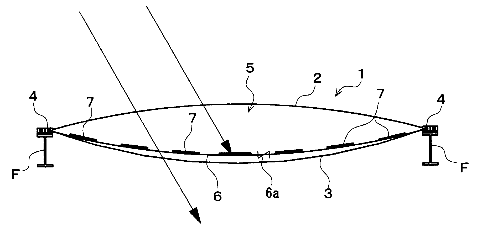
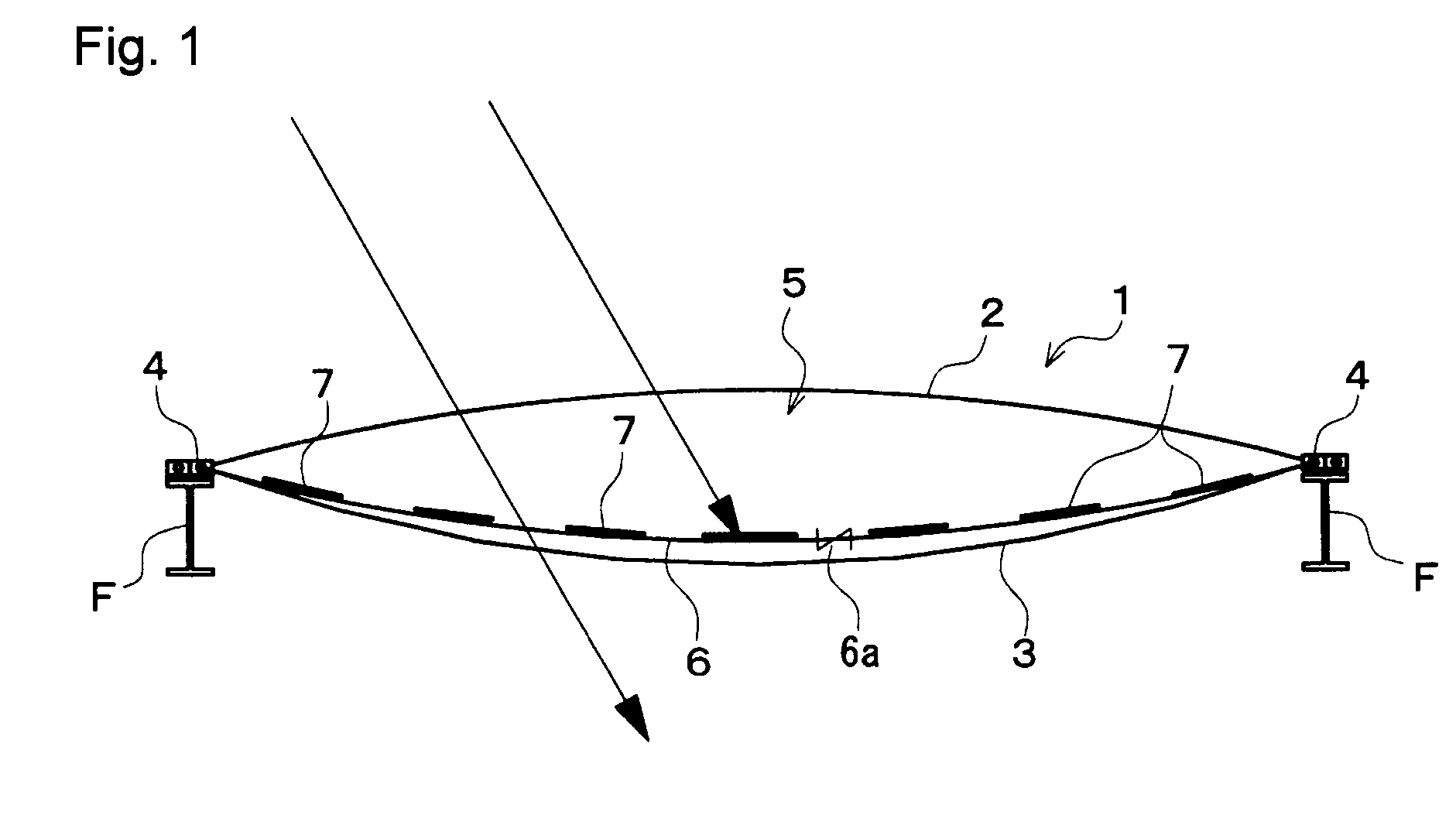
[0050]In these Figs., the roof structure of a building C is schematically constituted by providing a plurality of solar battery modules 7 inside a pneumatic panel 1.

[0051]That is, the pneumatic panel 1 comprises an outer film material 2 and an inner film material 3 formed in two rectangle sheets, each made of a transparent plastic film material such as an ethylene / tetrafluoroethylene copolymer (hereinafter referred to as ETFE), air-tightly integrated along the respective peripheries, and held by a peripheral frame 4. As a result, an inner space 5 is created between the outer film material 2 and the inner film material 3. Further, the roof of the building C is constituted by a plurality of such pneumatic panels 1 supported by the peripheral frame 4 in such a manner that the respective...


PUM


Abstract

To provide an enclosure structure for a building, which can maintain a high power generation efficiency without formation of irregularities on the surface of the enclosure such as a roof, nor application of an external force to solar battery modules, and which can form a lightweight enclosure capable of photovoltaic generation.An enclosure structure for a building, comprising an outer film material made of a light transmitting material and arranged on the outer surface side of the building, an inner film material arranged along inside of the outer film material, an intermediate film material disposed between the outer film material and the inner film material, an air supply means for supplying air to the space between the outer film material and the inner film material, and solar battery modules 7 provided on the inner surface of the intermediate film material.

Description

CROSS-REFERENCE TO RELATED APPLICATIONS[0001]This application is a continuation of PCT / JP2008 / 073831 filed Dec. 26, 2008, which claims priority to Japanese Application No. JP2007-335655 filed Dec. 27, 2007. The contents of each of the above applications are incorporated herein by reference.TECHNICAL FIELD[0002]The present invention relates to an enclosure structure for various buildings such as an atrium and a greenhouse, which has a double film structure and has a power generation function by the sunlight.BACKGROUND ART[0003]In recent years, from demands for environmental protection and energy saving, a technique of installing solar battery modules on a roof which is one type of an enclosure for a building and converting the sunlight energy which is natural energy to electric power to use it as a power resource for inside of the building and also to sell remained power, is in practical use.[0004]On the other hand, as the roof structure, a structure composing the roof by disposing a...

Claims


Application Information

Patent Timeline
Patent Type & Authority Patents(United States)
IPC IPC(8): H01L31/042E04H15/20H01L31/048E04D13/18
CPCE04H15/20A01G9/1415A01G9/243H02S20/00F24J2/5271E04H2015/203Y02B10/12Y02E10/50Y02E10/47Y02B10/20H02S20/20F24S20/80Y02A40/25Y02P60/12Y02B10/10
Inventor NISHIKAWA, KAORUNAKAO, TAKUYA
Owner ASAHI GLASS CO LTD
Learn More