Linear shaped charge system

a charge system and linear shape technology, applied in the direction of explosive charges, weapons components, ammunition projectiles, etc., can solve the problems of ineffective more conventional means of forced entry by the use of rams or sledgehammers and the like, inability to apply rigid metal liners to curved surfaces, and the risk of injury to the occupants of the building or even the operational personnel

Inactive Publication Date: 2012-04-03
METHOD OF ENTRY TECH PTY LTD WRIGHTS ACCOUNTANTS
View PDF23 Cites 15 Cited by
  • Summary
  • Abstract
  • Description
  • Claims
  • Application Information

AI Technical Summary

Problems solved by technology

In such situations the more conventional means of forced entry by the use of rams or sledge hammers and the like may be rendered ineffective by the particular structural or barricaded entry conditions of the building.
These are high risk operations, with known methods making use of metal fragments to effect penetration at the desired point of entry, with risk of injury to the occupants of the building, or even of the operational personnel.
Thus those systems which employ rigid metal liners cannot be applied to curved surfaces and the metal ejecta generated by the liner presents a danger to personnel.
Malleable linear charges are known but only allow relatively limited bending.

Method used


Image

  • Linear shaped charge system
  • Linear shaped charge system
  • Linear shaped charge system

Examples


first preferred embodiment

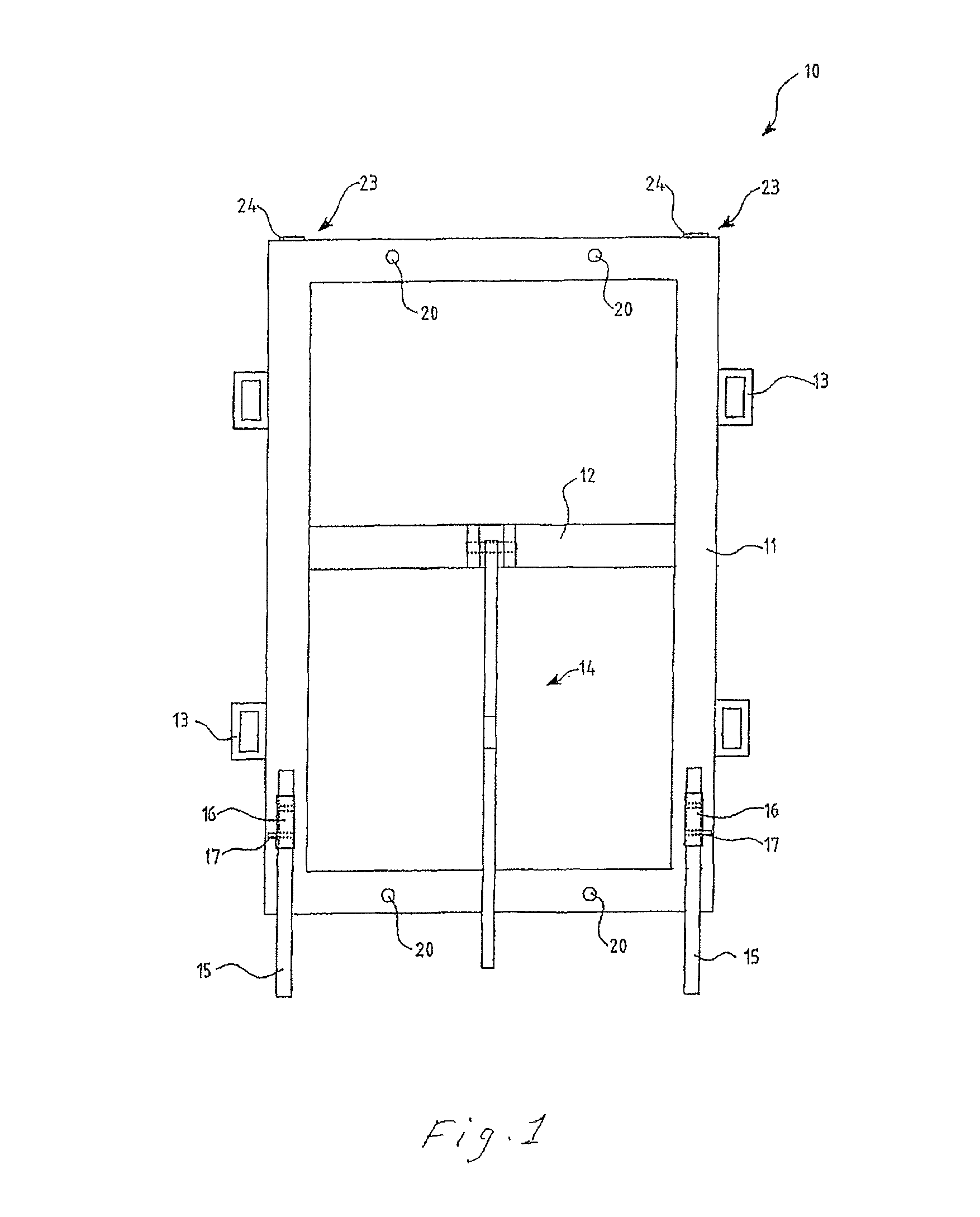
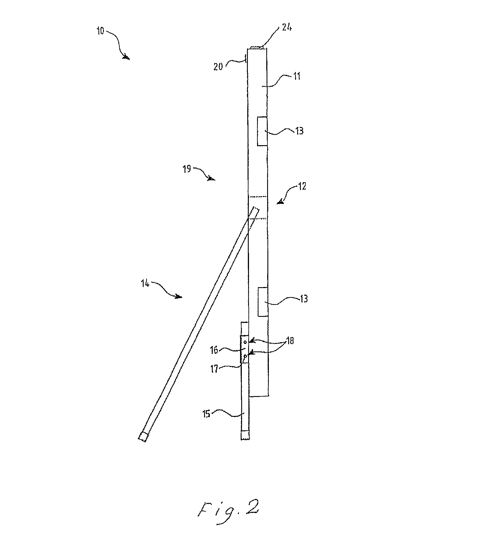
[0047]With reference now to FIGS. 1 and 2, a first preferred embodiment of a charge carrier (10) is particularly adapted to the penetration of masonry walls, including single, double and cavity brick walls, concrete block walls and light formed concrete walls. A perimeter frame (11) is formed of polymeric hollow section and includes at least one cross member (12). Carrier perimeter frame (11) may further be provided with carry handles (13) and a telescopically adjustable hinged support brace (14). Height adjustment of the frame may be provided by means of foot elements (15) sliding in sleeves (16) and located at a preferred height by locking pegs (17) passing through a plurality of holes (18) in sleeves (16).

[0048]Arranged at intervals on the rear face (19) of frame (11), that is that face directed away from the surface to be penetrated, is a plurality of charging ports (20) to allow for detonation of the explosive charge elements carried by the frame.

[0049]One preferred sectional s...

second preferred embodiment

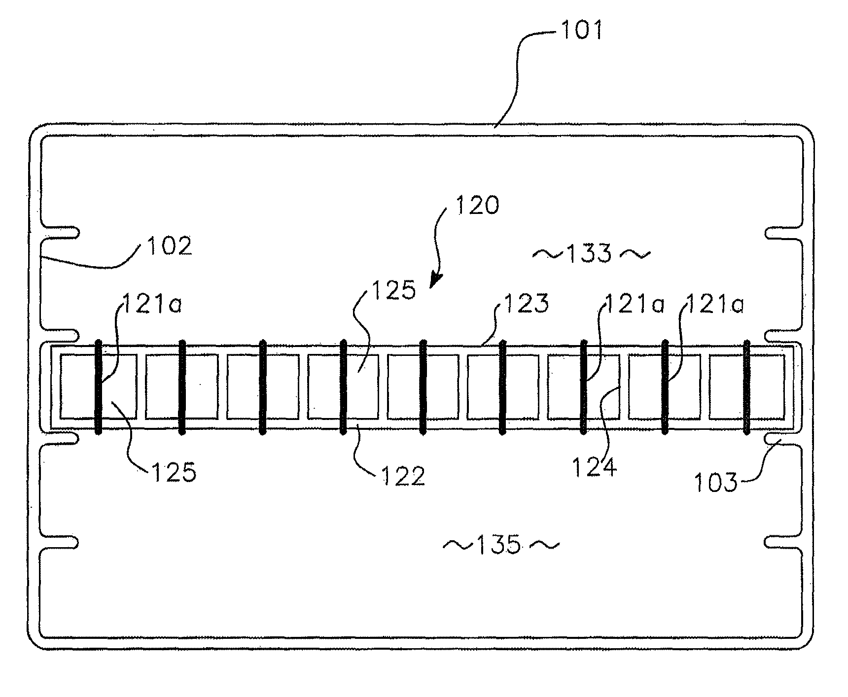
[0052]In a second preferred embodiment of a charge carrier according to the invention as shown in FIGS. 5 and 5A, carrier 100 is adapted to effect a directed explosive charge in which a fluid such as water acts as a tamping agent and at least partly as the penetrating agent. In this arrangement a first volume (133) of the tamping fluid is positioned rearward of an explosive charge element (120) and a second volume (135) of the tamping fluid is positioned forward of the explosive charge element.

[0053]This second preferred embodiment is adapted in particular to any of a variety of door constructions, including commercial or domestic metal roller doors, metal doors, fire doors, reinforced timber doors and glass doors. It may also be used for some wall structures.

[0054]As shown in FIGS. 5 and 5A, charge carrier (100) has an elongate body (101) preferably formed of an extruded polymer section (as can best be seen in FIG. 6), although it may also be formed as a casting or fabrication. The...


PUM


Abstract

A linear charge system (100) for applying a destructive explosive charge to a barrier structure; said system comprising a charge carrier (101) and an explosive charge element (120) assembled within said charge carrier (101); said explosive charge element (120) adapted to effect a directed explosive charge for the penetration of a said barrier in which a tamping fluid forms at least a portion of a penetrating agent.

Description

[0001]This application is a continuation-in-part of application Ser. No. 10 / 536,468 filed on Mar. 27, 2006 now U.S. Pat. No. 7,536,956, which is a 371 of International Application AU03 / 001585 filed on Nov. 28, 2003, which designated the U.S., claims the benefit thereof and incorporates the same by reference.[0002]The present invention relates to systems and methods adapted to shaped charge systems for the controlled application of a destructive explosive charge and, more particularly for the gaining of forced entry into buildings and structures in situations where such entry is required for military or law enforcement purposes and where such entry is denied.BACKGROUND[0003]In both military and law enforcement operations it may become necessary to gain forced entry into buildings where such entry by normal means is denied. Some examples of such situations may include the rescue of hostages or the interdiction of serious criminal activity. In such situations the more conventional mean...

Claims


Application Information

Patent Timeline
Patent Type & Authority Patents(United States)
IPC IPC(8): F42B12/00
CPCC06B45/00C06C5/04F42B1/028F42B1/032F42B1/036
Inventor MURRAY, CHRIS JOHNALLMAN, SCOTT MAXWELL
Owner METHOD OF ENTRY TECH PTY LTD WRIGHTS ACCOUNTANTS
Why Eureka
Try Eureka