
Ink jet printing apparatus and ink jet printing method

a printing apparatus and ink jet technology, applied in printing, other printing apparatus, etc., can solve the problems of ink ejection performance degradation, residue accumulation, landing position error, etc., and achieve the effect of reducing the volume of waste ink discarded

Active Publication Date: 2012-04-03
CANON KK
View PDF29 Cites 3 Cited by
  • Summary
  • Abstract
  • Description
  • Claims
  • Application Information

AI Technical Summary

Benefits of technology

[0013]The present invention provides an ink jet printing apparatus and an ink jet printing method capable of performing a recovery operation at an optimal timing while at the same time reducing a volume of waste ink discarded by the recovery operation of the print head.
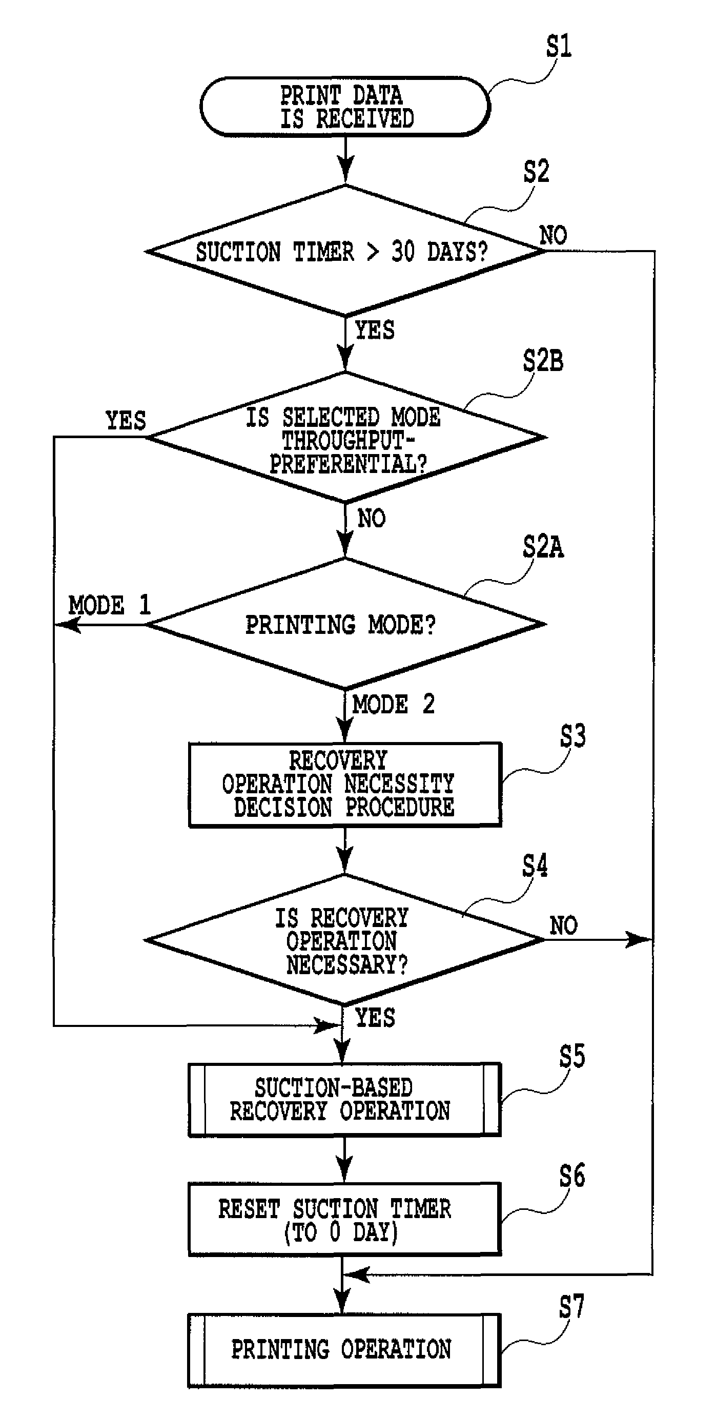
[0016]With this invention, a recovery operation of the print head, which is performed, after a predetermined period has elapsed, prior to a print operation that forms an image on a print medium, if information on the ink ejection state of the print head satisfies a predetermined condition. This makes it possible to perform the recovery operation at an optimal timing while at the same time reducing a volume of waste ink discarded by the recovery operation of the print head.

Problems solved by technology

When a bubble is present in a nozzle or liquid path of such a print head, an ink ejection performance of the print head may deteriorate.
More specifically, the presence of a bubble may result in an ink droplet failing to be ejected from the print head or an ejected ink droplet deflecting from an intended direction, causing a landing position error.
Also in a print head that ejects ink by an expanding force of a generated bubble, there is also a possibility that minute air residues may accumulate to form a bubble in the nozzle.
This automated timer recovery control, however, has the following problem.
This in turn increases a running cost and makes it necessary to increase a waste ink tank for collecting the discharged ink.
So, the recovery operation is performed more than necessary, which in turn increases the volume of ink consumed by the recovery operations.
Reducing the volume of waste ink that is discarded more than necessary is now a grave issue in terms of the running cost.
Particularly, for a user who prints an image only rarely, since the volume of ink actually used for printing is not so large, a ratio of the ink volume discarded by the recovery operation to the total ink consumption becomes high.
For such a user, the running cost is even higher.
In that case, although the ink volume discarded by the recovery operation can be reduced substantially, the print head's ejection performance will likely deteriorate because no recovery operation is executed.
When the ejection performance of the print head deteriorates, a quality of printed image will also deteriorate.
However, depending on the condition of use of the printing apparatus by the user, the ejection performance of the print head may deteriorate.
Therefore, it is difficult to perfectly guarantee the ejection performance of the print head depending on the environment of use of the printing apparatus and the printing state.

Method used


Image

  • Ink jet printing apparatus and ink jet printing method
  • Ink jet printing apparatus and ink jet printing method
  • Ink jet printing apparatus and ink jet printing method

Examples


Embodiment Construction

[0029]Now embodiments of this invention will be described in detail by referring to the accompanying drawings.

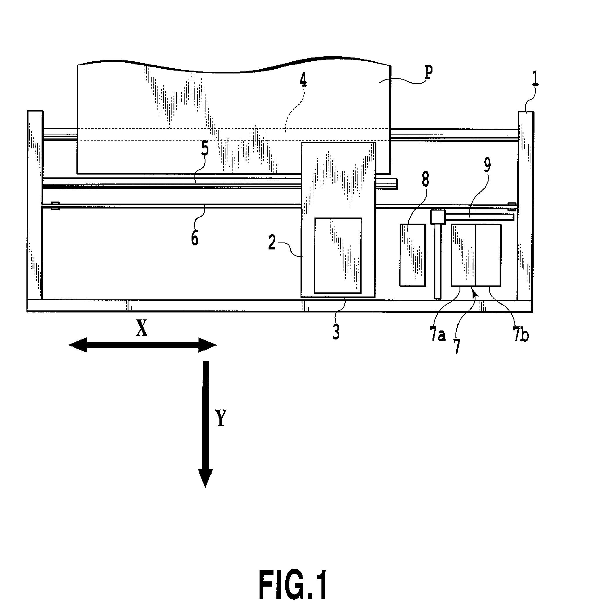
[0030]FIG. 1 is a plan view showing a mechanical construction of the ink jet printing apparatus to which the present invention can be applied.

[0031]In FIG. 1, reference numeral 1 represents a printing apparatus body having a variety of mechanisms. Among the mechanisms is a conveying unit (not shown) that conveys a print medium P, such as print paper, in a sub-scan direction of arrow Y. The printing apparatus body 1 and a control system described later that is mounted in the printing apparatus body constitute an ink jet printing apparatus. The ink jet printing apparatus in this embodiment is of a serial type, which forms an image on a print medium P by intermittently conveying the print medium P in the sub-scan direction by the conveying unit and by performing a printing scan of an ink ejection print head 3 as it moves in a main scan direction of arrow X. The print head 3 is ...


PUM


Abstract

An ink jet printing apparatus and an ink jet printing method are provided which can perform ink ejection performance recovery operations on a print head at optimal timings while at the same time reducing a volume of ink discarded by the recovery operations. Thirty days after a previous recovery operation, a suction-based recovery operation is performed on the print head prior to the printing operation that forms an image on a print medium. The recovery operation is performed under the condition that a temperature increase of the print head caused by a preliminary ejection of the print head is not more than a predetermined value.

Description

BACKGROUND OF THE INVENTION[0001]1. Field of the Invention[0002]The present invention relates to an ink jet printing apparatus and an ink jet printing method to form an image on a print medium using a print head that has a plurality of ink ejection openings.[0003]2. Description of the Related Art[0004]In an ink jet printing apparatus that forms an image on a print medium by ejecting ink droplets, a print head is used that has a plurality of fine ink ejection openings and liquid paths communicating to the openings (a combination of each ink ejection opening and its associated liquid path is also called a “nozzle”). When a bubble is present in a nozzle or liquid path of such a print head, an ink ejection performance of the print head may deteriorate. More specifically, the presence of a bubble may result in an ink droplet failing to be ejected from the print head or an ejected ink droplet deflecting from an intended direction, causing a landing position error. A bubble may be produced...

Claims


Application Information

Patent Timeline
Patent Type & Authority Patents(United States)
IPC IPC(8): B41J2/165
CPCB41J2/16517B41J2/1404B41J2/14129B41J2/14233B41J29/393
Inventor HARA, KATSUSHI
Owner CANON KK
Learn More