Device for cauterising tissue and uses thereof

a tissue and device technology, applied in the field of cauterising tissue devices, can solve the problems of uncontrollable bleeding, paucity of devices created to prevent uncontrolled bleeding, and difficulty in image-guided minimally invasive biopsy techniques, so as to promote a “clean” insertion of the device and reduce the effect of drag

Active Publication Date: 2012-04-03
JABEZ HOPE PTE
View PDF19 Cites 1 Cited by
  • Summary
  • Abstract
  • Description
  • Claims
  • Application Information

AI Technical Summary

Benefits of technology

[0015]The device may be as thin as possible, such as within the thickness range of between 0.1 to 0.5 mm. In so doing, on insertion of the instrument, the device may have a minimal “drag”, or “snow plough” effect, on the adjacent tissue and skin, and instead promote a “clean” insertion of the device.

Problems solved by technology

This often results in bleeding which may occasionally be uncontrolled.
It is evident that because of its approach, bleeding poses a challenge for image-guided minimally invasive biopsy techniques as haemostasis cannot be achieved in the traditional manner as would be possible in conventional biopsies.
There is a paucity of devices created to prevent uncontrolled bleeding in a consistent and effective manner following percutaneous minimally invasive biopsies.
Although some of these techniques have been proven useful in conventional surgery, the requirements for negotiating the tract from the skin to the lesion before its application precludes its accurate and effective use in the setting of minimally invasive percutaneous biopsy techniques.
Based on current methods, effective haemostasis may not be achieved and continued bleeding or a large haematoma might result.

Method used


Image

  • Device for cauterising tissue and uses thereof
  • Device for cauterising tissue and uses thereof
  • Device for cauterising tissue and uses thereof

Examples


Embodiment Construction

[0051]It will be convenient to further describe the present invention with respect to the accompanying drawings that illustrate possible arrangements of the invention. Other arrangements of the invention are possible, and consequently the particularity of the accompanying drawings are not intended to be limiting of the present invention.

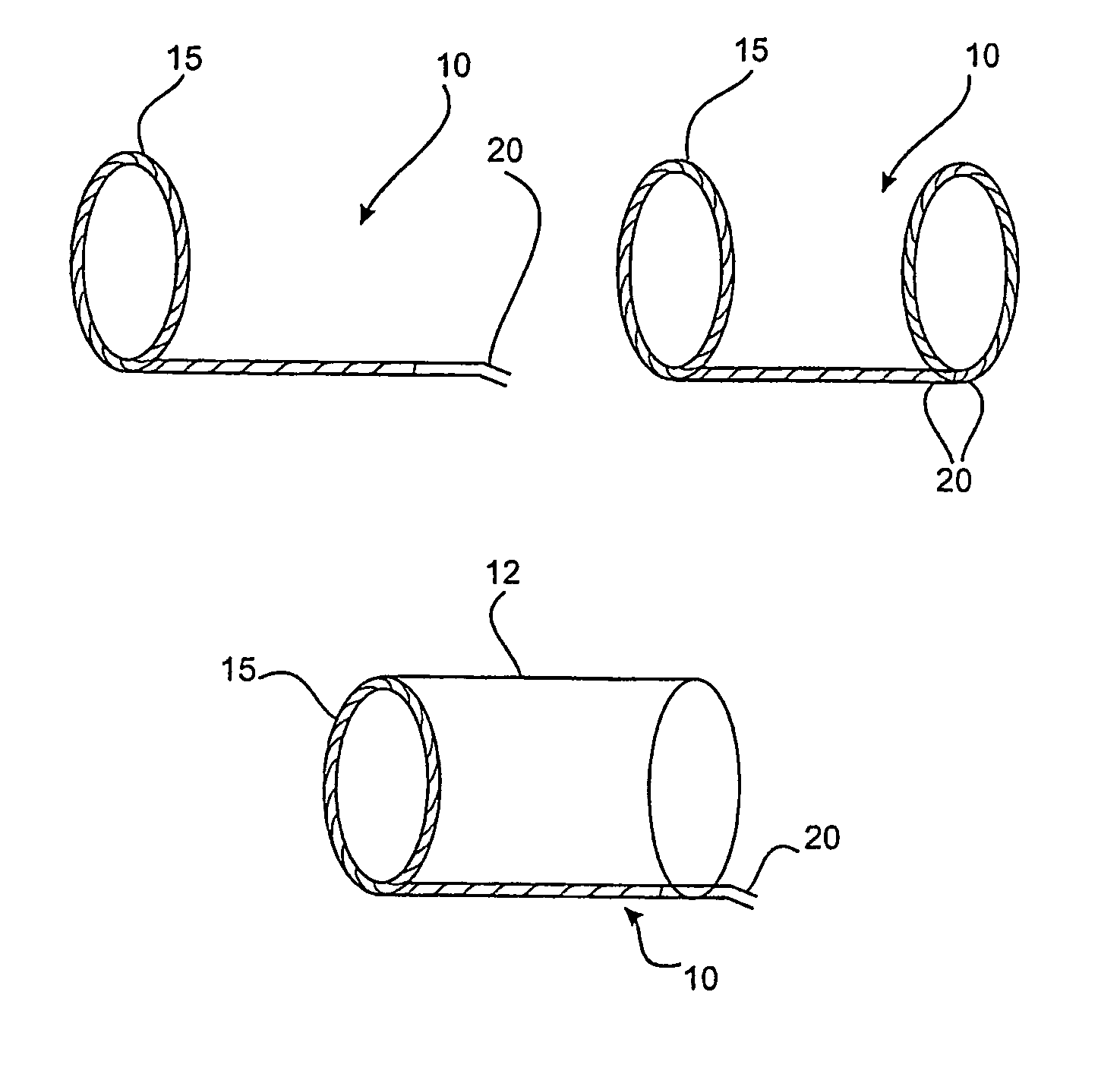
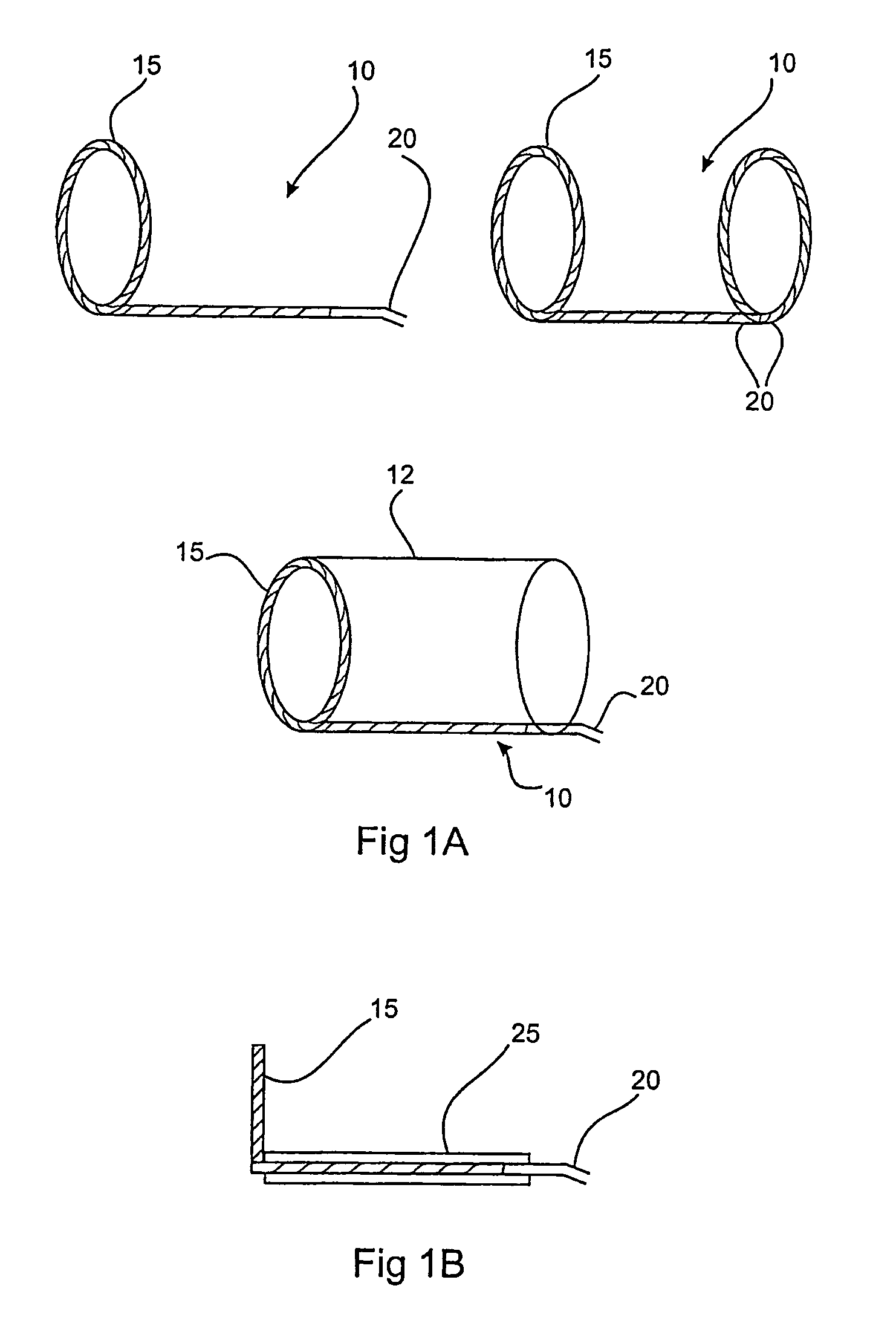
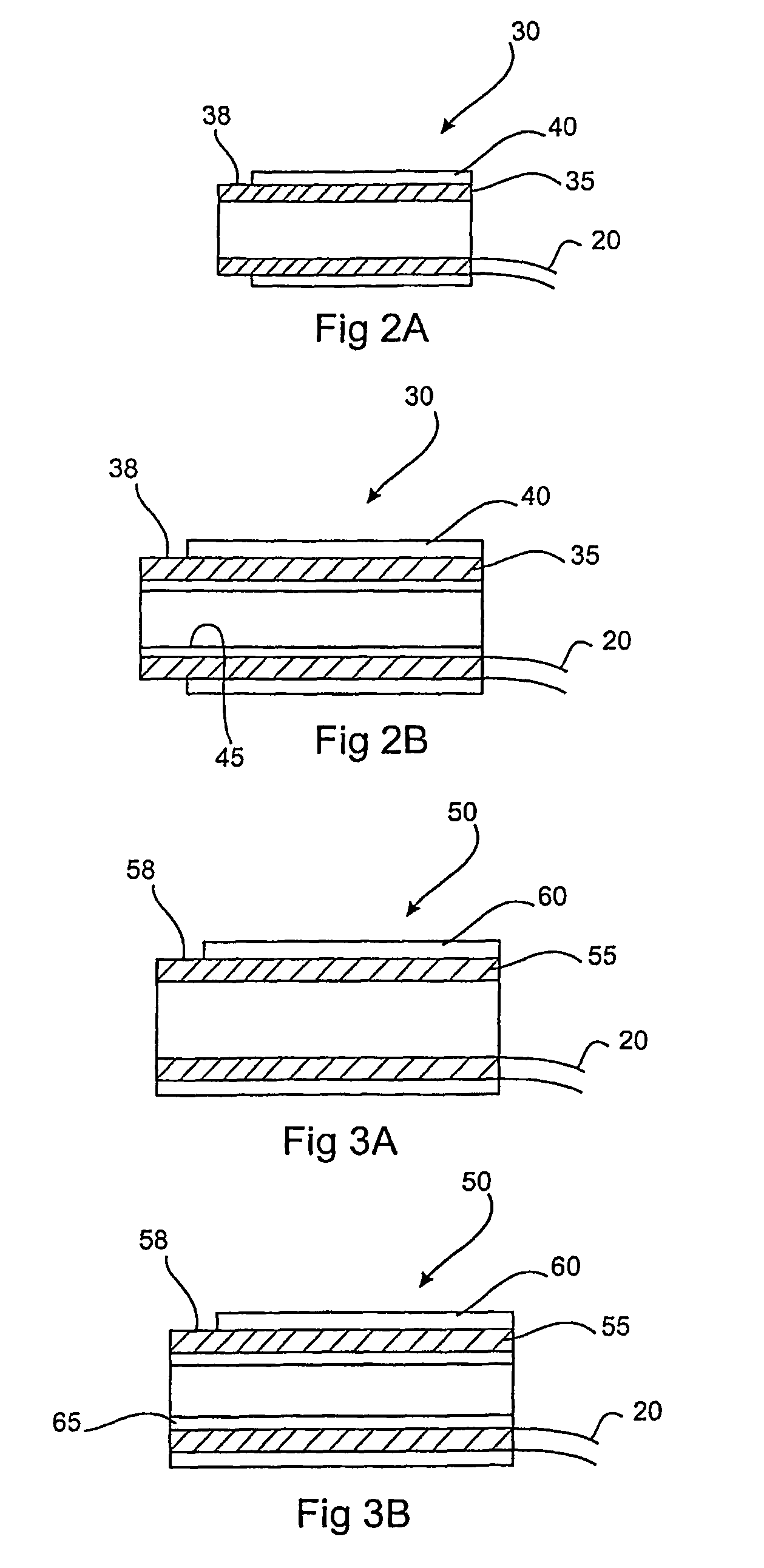
[0052]According to a first aspect, the present invention provides a device for cauterising tissue, the device arranged to be mounted to a biopsy and / or sampling instrument and comprising a conductive cauterising portion and means for heating the cauterising portion.

[0053]The biopsy and / or sampling instrument to which the device may be mounted to can be any biopsy and / or sampling instrument known in the art. For example, the instrument may be any one of the instruments as described by U.S. Pat. Nos. 5,526,822, 5,649,547, 5,769,086, 6,638,235, herein incorporated by reference.

[0054]According to a further aspect, the device is hollow. For the purposes o...


PUM

PropertyMeasurementUnit
lengthaaaaaaaaaa
diameteraaaaaaaaaa
thicknessaaaaaaaaaa

Abstract

The present invention provides a device for cauterising tissue, the device arranged to be mounted to a biopsy and / or sampling instrument and including a conductive cauterising portion and means for heating the cauterising portion. The device may be mounted either permanently or releasably removable from the biopsy and / or sampling instrument.

Description

CROSS REFERENCE TO RELATED APPLICATIONS[0001]This application is a 371 national stage filing of PCT International Application No. PCT / SG2005 / 000369, filed on 25 Oct. 2005, and published in English on 4 May 2006, as WO 2006 / 046931 A2, which claims priority to Singaporean Application No. 200406874-8 filed on 26 Oct. 2004, the entire disclosures of which are incorporated herein by reference.FIELD OF THE INVENTION[0002]The present invention relates to a device for cauterising tissue suitable to be mounted on a biopsy and / or sampling instrument.BACKGROUND OF THE INVENTION[0003]The sampling of a portion of a tissue is often necessary in many humans and animals, particularly in the diagnosis and treatment of patients with cancerous tumours, pre-malignant conditions and other diseases and disorders. In particular, it is used to exclude malignancy. A biopsy may be performed when a lesion, or an abnormal area within a tissue that could possibly represent cancerous changes, is detected. The bi...

Claims


Application Information

Patent Timeline
Patent Type & Authority Patents(United States)
IPC IPC(8): A61B18/08
CPCA61B10/0233A61B10/0275A61B18/082A61B10/04Y10T29/49826A61B2017/00991A61B2018/00595A61B2018/1407
Inventor TAN, POH CHOO MONA
Owner JABEZ HOPE PTE
Why Eureka
Try Eureka