Gas and Oil Sealing in a Rotary Valve
a technology of gas and oil sealing and rotary valves, which is applied in the direction of valve arrangements, oscillatory slide valves, machines/engines, etc., can solve the problems of inability to design a satisfactory gas and oil sealing arrangement, large total leakage gap, and no commercial success
- Summary
- Abstract
- Description
- Claims
- Application Information
AI Technical Summary
Benefits of technology
Problems solved by technology
Method used
Image
Examples
second embodiment
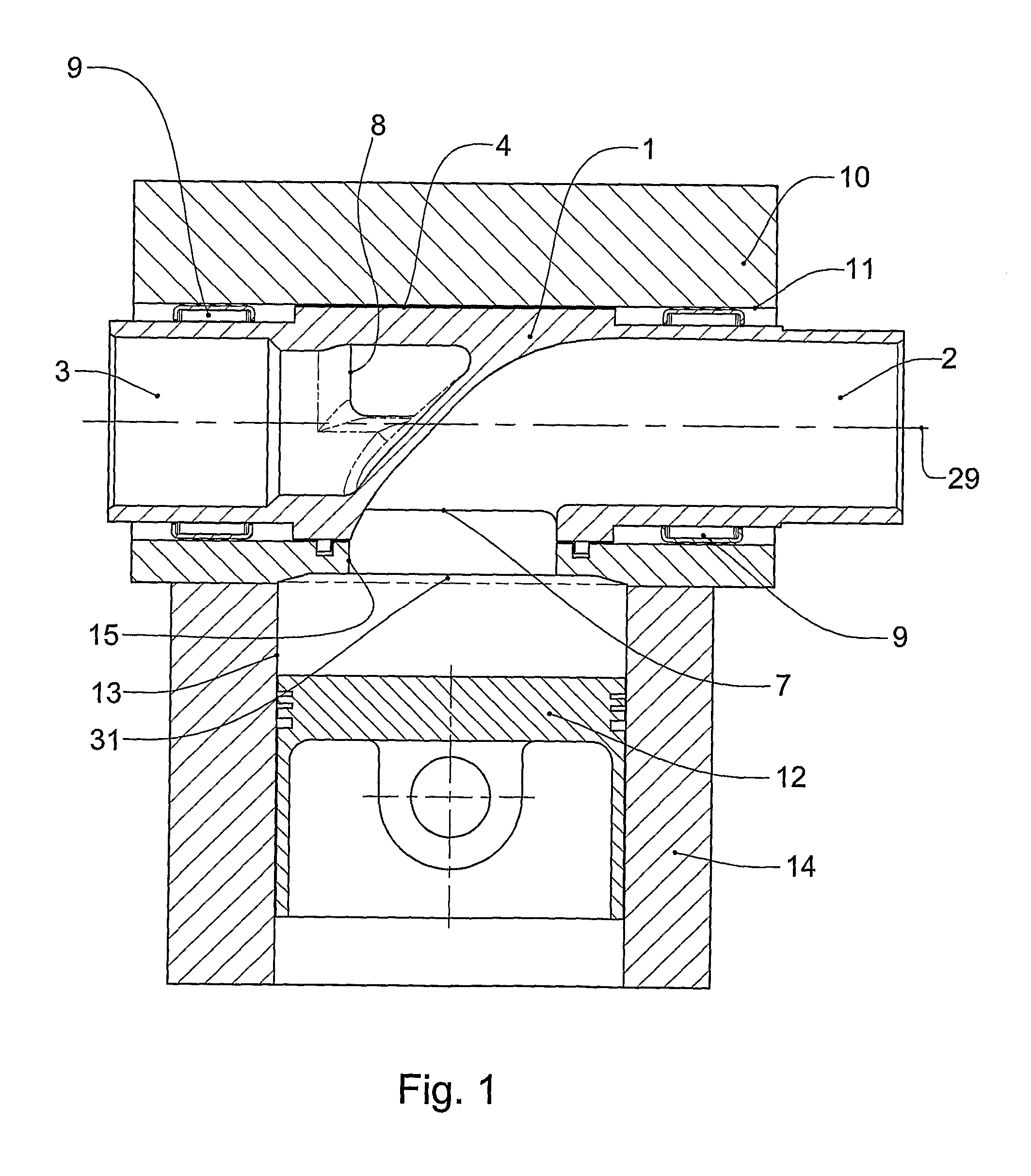
[0100]FIG. 7 is a part section through the centre of one end of an axial slot 18 of a rotary valve assembly in accordance with the present invention, showing details of an alternative spring design. Spring 21c is different to that previously shown in that the upper leg 41c is shorter than the lower leg 42c. Spring 21c has the advantage that it maximises the allowable spring movement whilst maintaining the line of action of the spring on axial seal 16 close to or outside openings 7, 8 and maintaining an acceptable stress level within the spring. The short upper leg 41 applies the radial load to axial seal 16 outside openings 7, 8. The longer lower leg 42 provides the necessary radial movement required to ensure an adequate spring force is applied to axial seal 16 in all operating conditions.
[0101] A function of the springs 21 as described above is to block the flow of combustion gases between the undersides 5 of the axial seals 16 and the roots 6 of the axial slots 18 to the area bet...
third embodiment
[0102] In the event that further reduction in the TELA is required, additional flexible elements may be introduced above springs 21. the present invention shown in FIG. 9 has flexible elements in the form of cylindrical seals 28 which are located above and in contact with springs 21. Cylindrical seals 28 are disposed in recesses formed in the underside of the ends of axial seals 16c. Cylindrical seals 28 have a width close to that of axial slots 18 and are made from an elastomeric material such as rubber. When assembled, seals 28 span between the circumferentially innermost sides 24 and circumferentially outermost sides 20 of axial slots 18. Cylindrical seals 28 block the type F leakage area that feeds the type A & B leakage area. In the event there is 1 mm between the top of cylindrical seals 28 and the top of axial seals 16c, the feed area is approximately reduced to 4×(1×0.01)=0.04 mm2. The TELA of this arrangement is now 0.04 mm2 or less than that of a conventional piston ring. ...
fourth embodiment
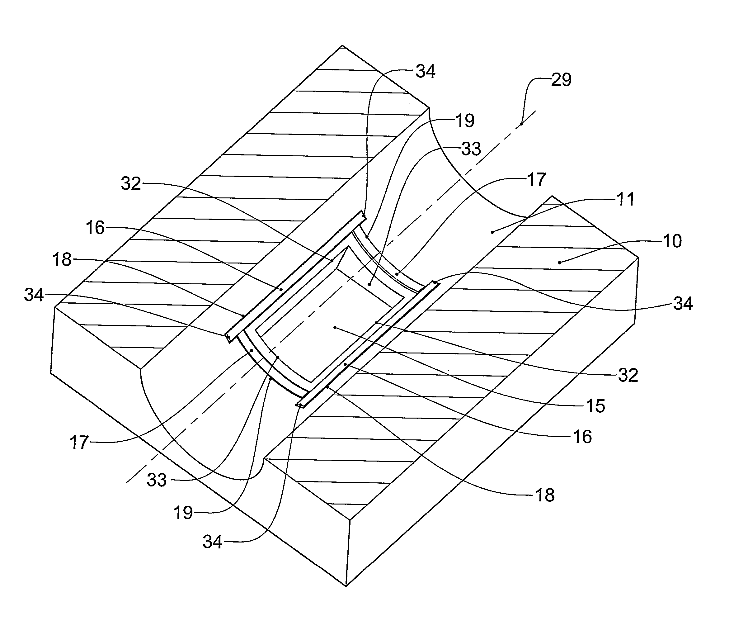
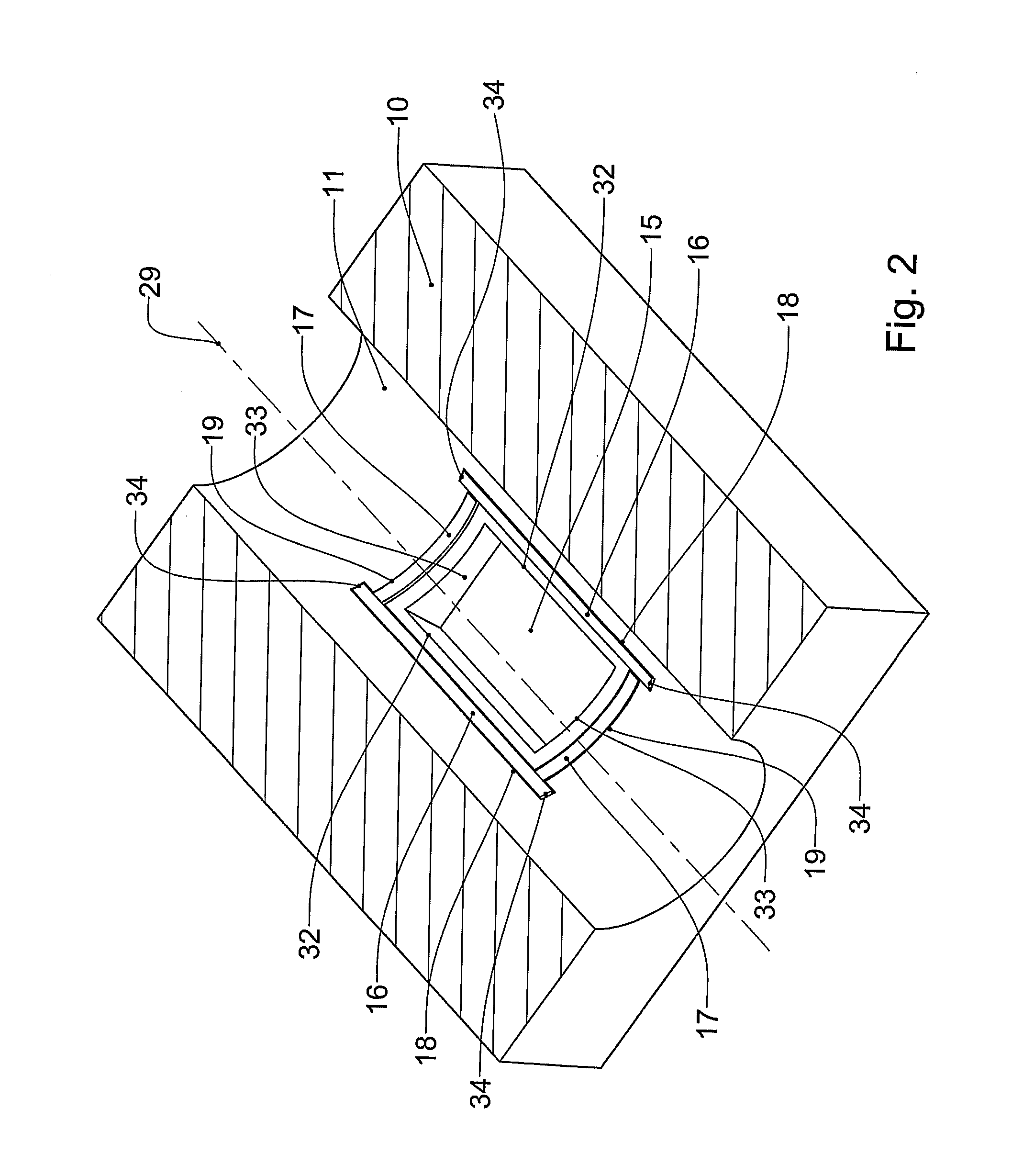
[0104]FIGS. 10 and 11 show sections of a rotary valve assembly in accordance with the present invention. FIGS. 10 and 11 are the same views as FIGS. 2 and 3 respectively, but with modifications added to enable mass production machining techniques to be utilised in the manufacture of the axial slots and circumferential seal slots. The seal slots previously discussed in reference to FIGS. 2 and 3 are square ended slots that require the use of techniques not generally associated with mass production to manufacture. Typically these square ended slots are manufactured using an EDM (electro discharge machining) process which is time consuming and expensive.
[0105] Bore 11a has been stepped at both ends of cylinder head 10. This radial step is deeper than the depth of axial slots 18a. Consequently axial slots 18a can be manufactured rapidly and economically by through-broaching the minimum diameter portion (i.e. the non-stepped portion) of bore 11a in the axial direction. After axial slots ...
PUM
 Abstract
Description
Claims
Application Information
 - R&D
- Intellectual Property
- Life Sciences
- Materials
- Tech Scout
- Unparalleled Data Quality
- Higher Quality Content
- 60% Fewer Hallucinations
Browse by: Latest US Patents, China's latest patents, Technical Efficacy Thesaurus, Application Domain, Technology Topic, Popular Technical Reports.
© 2025 PatSnap. All rights reserved.Legal|Privacy policy|Modern Slavery Act Transparency Statement|Sitemap|About US| Contact US: help@patsnap.com


