Substrate cleaning method and computer readable storage medium

a technology of computer readable storage medium and substrate, which is applied in the direction of cleaning process and apparatus, cleaning using liquids, chemical instruments and processes, etc., can solve the problems of increasing the absolute value of static build-up voltage generated on the cleaned substrate, affecting and affecting the cleaning effect of the substrate. , to achieve the effect of preventing the substrate from being broken and improving the throughput of the cleaning apparatus

Active Publication Date: 2012-04-03
TOKYO ELECTRON LTD
View PDF25 Cites 9 Cited by
  • Summary
  • Abstract
  • Description
  • Claims
  • Application Information

AI Technical Summary

Benefits of technology

[0004]An object of the present invention is to provide a substrate cleaning method that can suppress static build-up on a substrate, such as a semiconductor wafer. Another object of the present invention is to provide a computer readable storage medium used for an apparatus to conduct this substrate cleaning method.
[0007]The substrate cleaning method according to the first aspect does not include a rinsing process step, which is conventionally considered as being indispensable. Conventionally, it is commonly thought by persons skilled in the art that a process using a two-fluid, or alternatively using high pressure jet water or mega-sonic cleaning water (these fluids will be collectively referred to as “cleaning fluid”, hereinafter) should be followed by a rinsing process using purified water. One of the reasons for this resides in that a rinsing process is indispensable in brush-scrub cleaning, which was in the mainstream before processes using the cleaning fluid described above have been adopted. Even though process modes have been changed from brush cleaning to non-brush cleaning, persons skilled in the art still follow the process steps of brush-scrub cleaning, without considering omission of the rinsing process. Further, it is commonly thought by persons skilled in the art that, where a rinsing process using purified water is performed, particles and so forth contained in a purified water film on the substrate are removed, so the cleaning accuracy is improved.
[0017]Conventionally, the rinsing process is performed while supplying purified water onto the center of the substrate being rotated. However, the inventor has found that, in this case, the absolute value of static build-up voltage becomes larger at the central portion of the substrate. In the substrate cleaning method according to the second aspect, the purified water supply point is caused to travel in a radial direction, as described above. Consequently, it is possible to prevent the absolute value of static build-up voltage from being locally increased on the substrate, and to suppress the static build-up to be smaller and more uniform over the entire substrate.
[0018]In order to enhance the effect described above, the method preferably comprises setting a traveling speed of the supply point of the purified water to be higher at a peripheral portion of the substrate than at a central portion thereof in performing the rinsing process, so as to equalize a processing time per unit area over the substrate. Alternatively, the method preferably comprises setting a rotation number of the substrate to be higher for the supply point of the purified water being present at a central portion of the substrate than at a peripheral portion thereof. The method preferably comprises rotating the substrate at a rotation number of 100 to 900 rpm, while supplying the purified water at a flow rate of 0.3 to 1.5 L / min, in performing the rinsing process. The purified water used in performing the rinsing process preferably contains carbon dioxide gas dissolved therein, by which the absolute value of static build-up voltage is further decreased.
[0022]According to the present invention described above, since the static build-up on a substrate is suppressed, it is possible to prevent the substrate from being broken and to protect circuits and so forth formed on the surface of the substrate. Further, where no rinsing process is performed, the throughput of the cleaning apparatus is advantageously improved.

Problems solved by technology

However, this cleaning method increases the absolute value of static build-up voltage generated on the cleaned semiconductor wafer.
Due to this voltage, the semiconductor wafer itself may be broken, or circuits formed on the surface of the semiconductor wafer may be damaged.

Method used


Image

  • Substrate cleaning method and computer readable storage medium
  • Substrate cleaning method and computer readable storage medium
  • Substrate cleaning method and computer readable storage medium

Examples


Embodiment Construction

[0036]Embodiments of the present invention will now be described with reference to the accompanying drawings, while taking a semiconductor wafer cleaning method as an example.

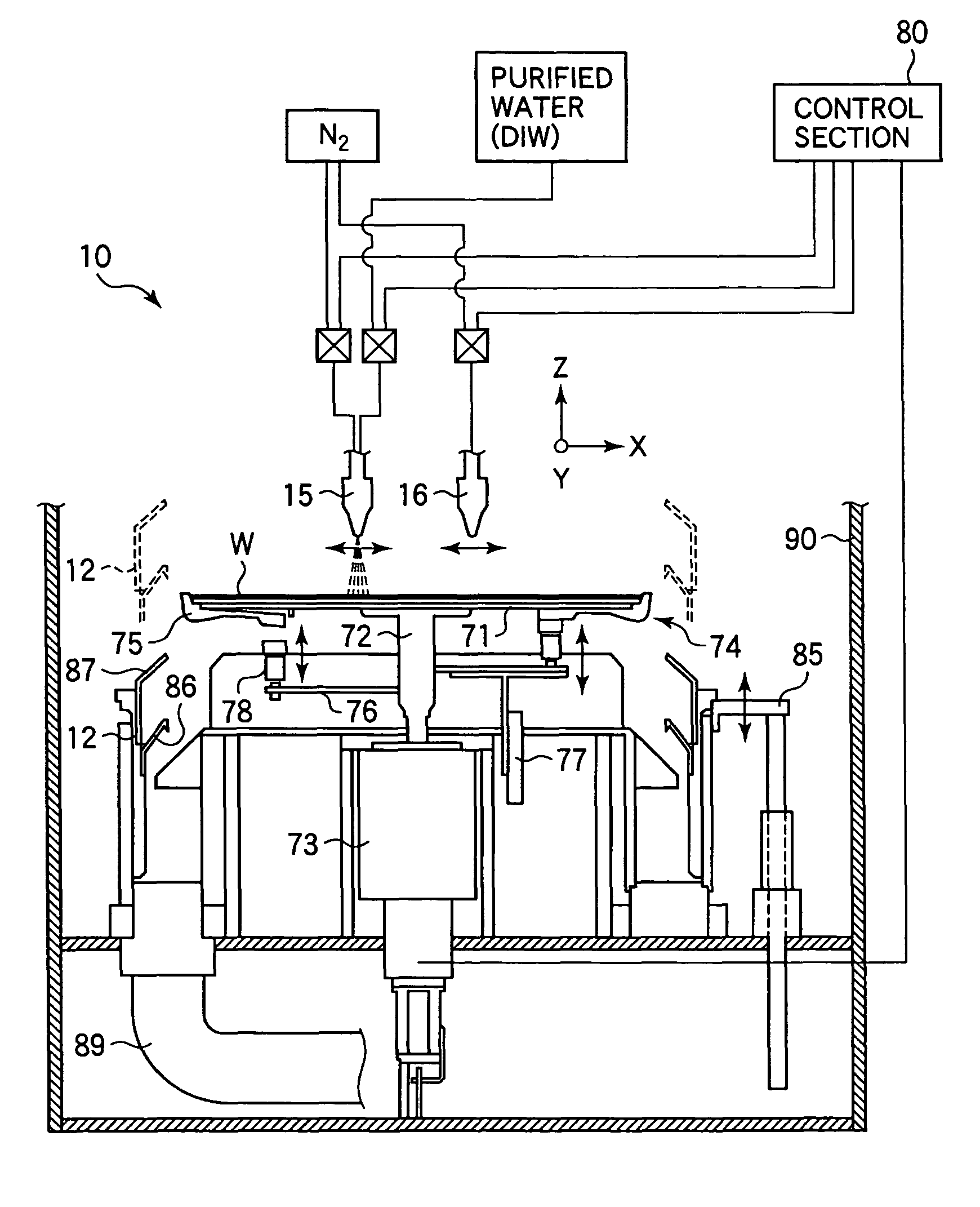
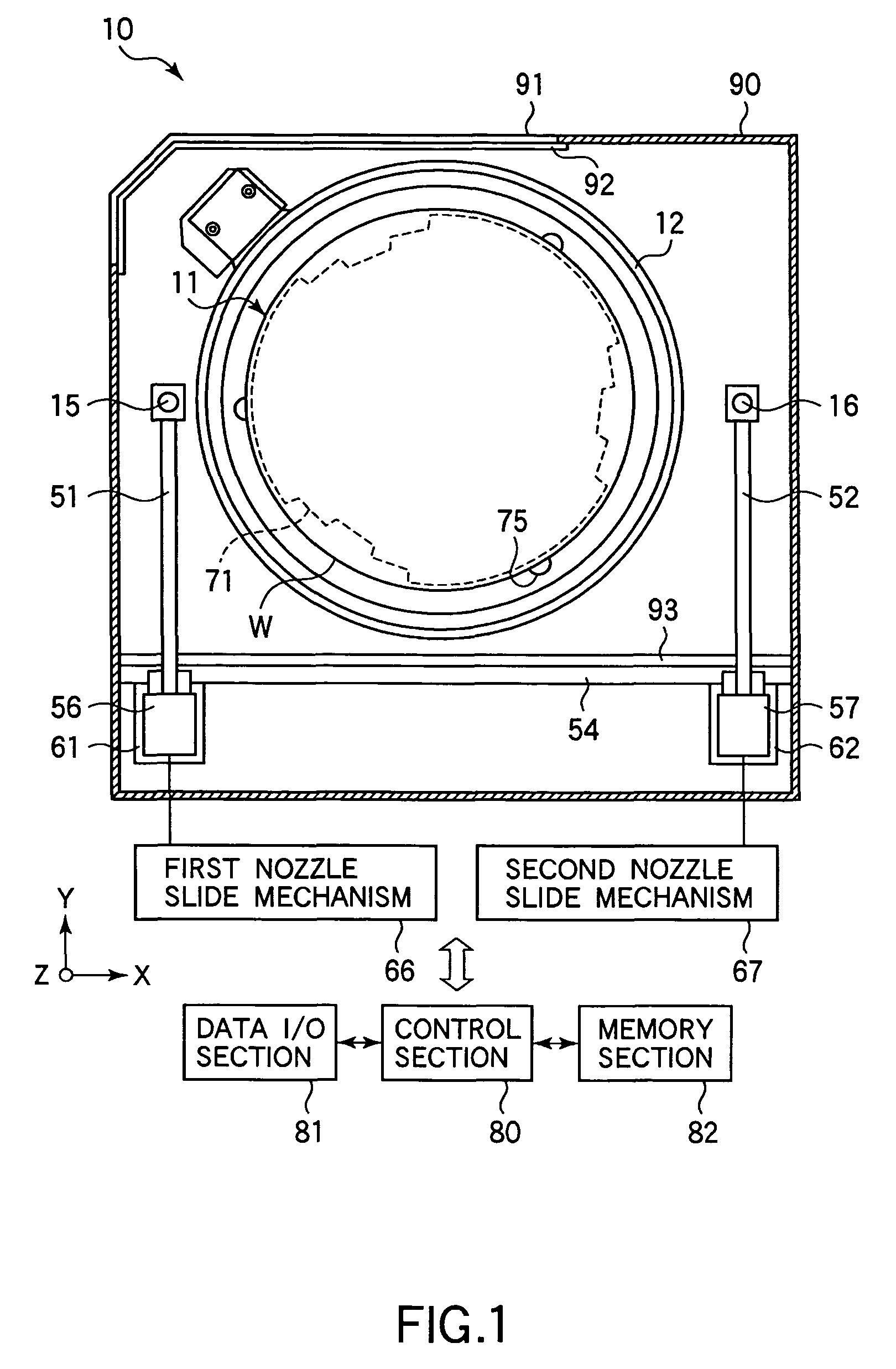
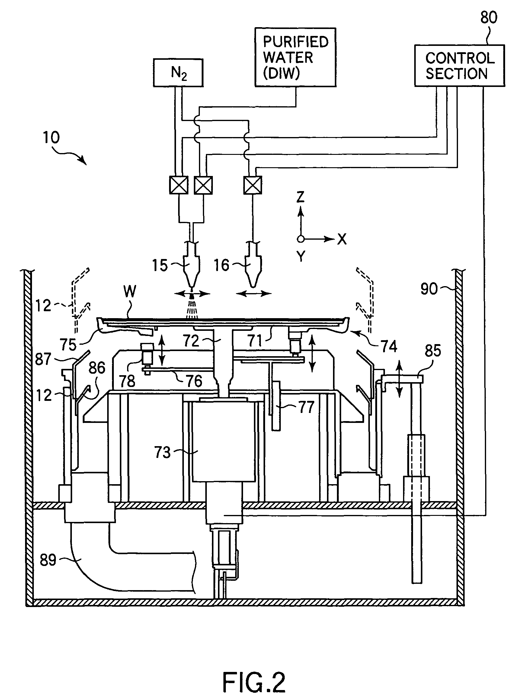
[0037]FIG. 1 is a plan view schematically showing the structure of a cleaning apparatus 10. FIG. 2 is a Z-X sectional view of the cleaning apparatus 10. FIG. 3 is a Y-Z sectional view of the cleaning apparatus 10. In this respect, the X-direction and Y-direction are perpendicular to each other in the horizontal plane, and the Z-direction is the vertical direction.

[0038]The cleaning apparatus 10 includes a housing 90, in which respective components are disposed. The housing 90 has a window portion 91 formed in one side and provided with a shutter 92 capable of opening / closing the window portion 91. The window portion 91 is used for loading and unloading a wafer W therethrough. The interior of the housing 90 is divided by a partition wall 93 into two chambers. As described later, one of the chambers is a liquid p...


PUM


Abstract

A wafer W is processed by supplying a two-fluid, high pressure jet water, or mega-sonic water onto the wafer W, while rotating the wafer W in an essentially horizontal state. After supply of the cleaning fluid is stopped, the wafer W is dried by rotating the wafer W at a higher speed than that used in supplying the cleaning fluid. No rinsing process using purified water is performed in a period after stopping supply of the cleaning fluid and before rotating the substrate at the higher speed.

Description

TECHNICAL FIELD[0001]The present invention relates to a substrate cleaning method for suppressing static build-up on a substrate, such as a semiconductor wafer, and a computer readable storage medium for controlling a substrate cleaning apparatus to conduct this substrate cleaning method.BACKGROUND ART[0002]For example, in the process of manufacturing semiconductor devices, a cleaning process is performed on a semiconductor wafer, as needed, to keep the surface of the semiconductor wafer clean. Jpn. Pat. Appln. KOKAI Publication No. 2003-168670 discloses a cleaning process of the single-wafer type, in which semiconductor wafers are processed one by one, as follows. Specifically, purified water is changed into mist by an inactive gas to obtain a fluid (i.e., a fluid of a so-called two-fluid type). The fluid thus obtained is supplied onto the surface of a semiconductor wafer, while the semiconductor wafer is rotated, to remove particles and so forth from the surface. Then, purified wa...

Claims


Application Information

Patent Timeline
Patent Type & Authority Patents(United States)
IPC IPC(8): B08B7/00B08B7/04B08B3/02H01L21/00H01L21/304H01L21/306
CPCB08B3/02H01L21/02052H01L21/67051B08B2203/0288Y10S134/902
Inventor SEKIGUCHI, KENJIOHNO, HIROKI
Owner TOKYO ELECTRON LTD
Why Eureka
Try Eureka