Power rail system

a power rail and power rail technology, applied in the field of firearms, to achieve the effect of maintaining a neutral balance of a firearm

Inactive Publication Date: 2012-04-10
WOLF PAC TECH CORP
View PDF21 Cites 74 Cited by
  • Summary
  • Abstract
  • Description
  • Claims
  • Application Information

AI Technical Summary

Benefits of technology

[0016]Accordingly, a feature and advantage of the present invention is its ability to eliminate the need for a battery disposed within the electric accessory.
[0017]Still another feature and advantage of the present invention is its ability to maintain a neutral balance of a firearm when an accessory is attached thereto.
[0018]Still another feature and advantage of the present invention is its ability to selectively supply a plurality of different voltages to power a corresponding one of a plurality of accessories, each potentially requiring a different voltage.
[0019]Still another feature and advantage of the present invention is its ability to enable adjustment of a position of an accessory on a firearm while maintaining a supply of power thereto.
[0020]Yet another feature and advantage of the present invention is its ability to provide a power rail comprising a plurality of removable and connectable sections for altering a length of the power rail.
[0021]Yet another feature and advantage of the present invention is its ability to be installed on a conventional firearm by replacing conventional components of the firearm.

Problems solved by technology

Backup sources of power may be necessary in some circumstances including, inter alia, if the primary power source voltage falls below a threshold level, or if a fault in the primary power source renders the primary power source unusable.

Method used


Image

  • Power rail system
  • Power rail system
  • Power rail system

Examples


Embodiment Construction

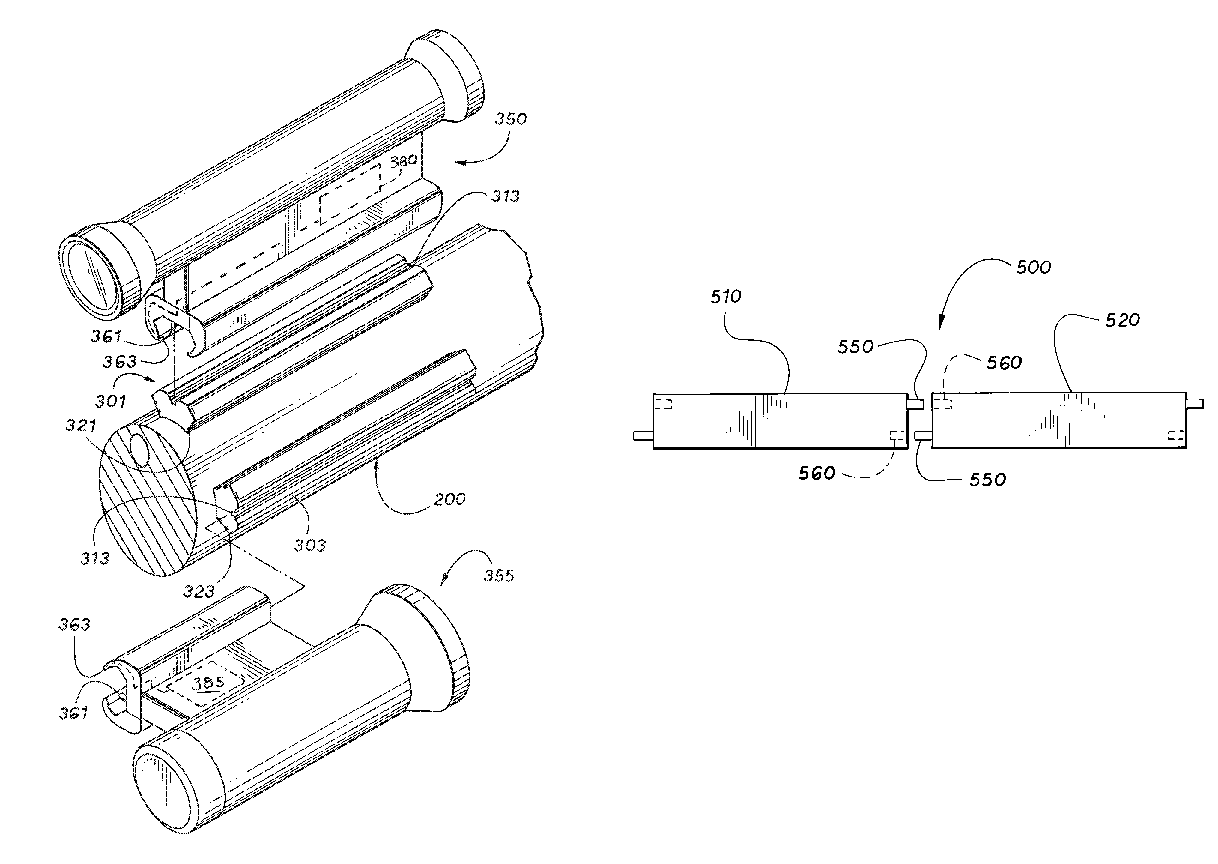
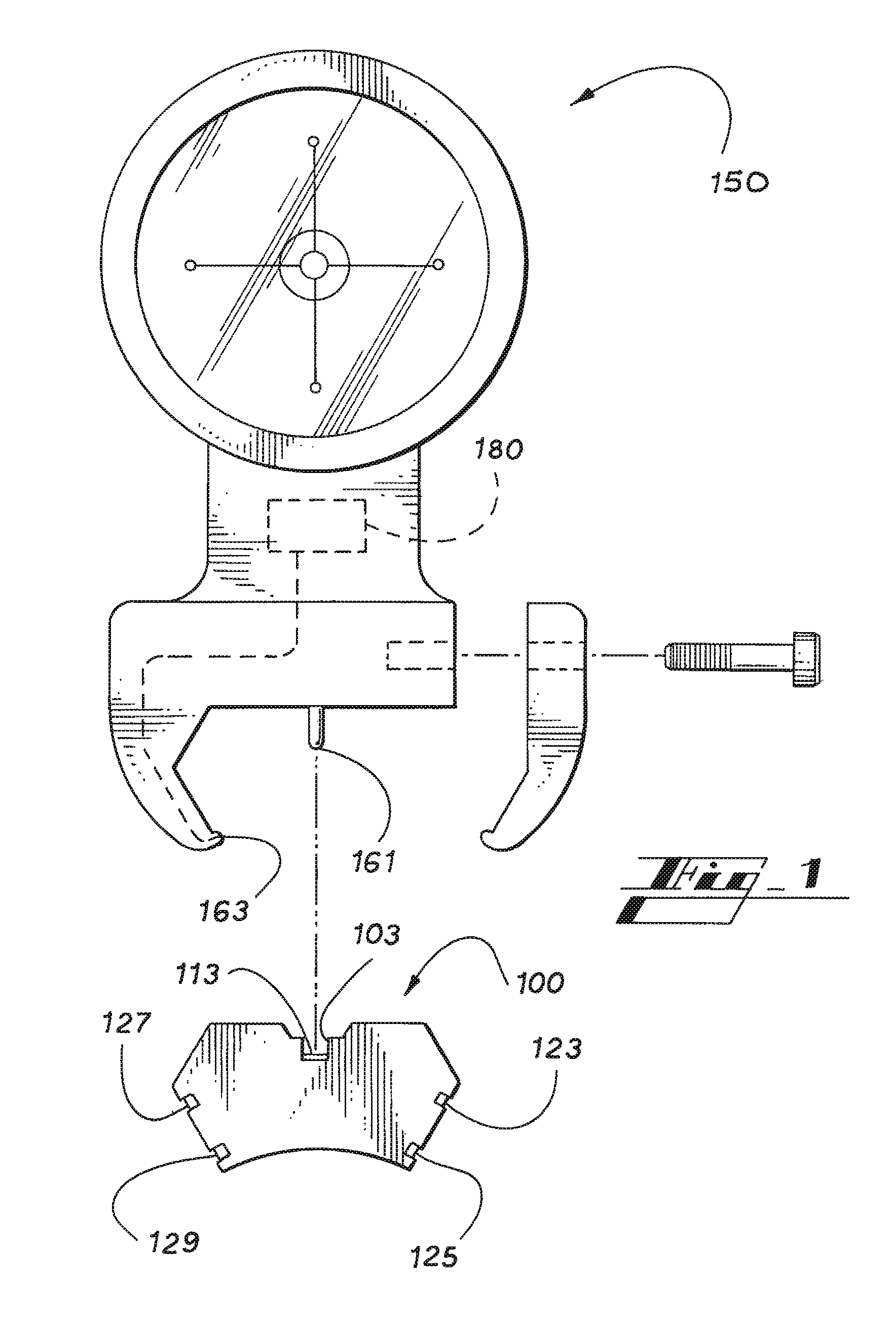
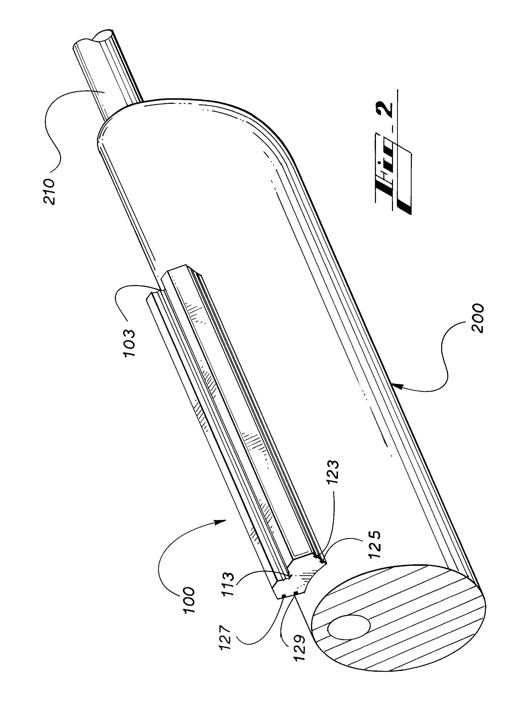
[0035]In describing the present invention, as illustrated in FIGS. 1-7, specific terminology is employed for the sake of clarity. The invention, however, is not intended to be limited to the specific terminology so selected, and it is to be understood that each specific element includes all technical equivalents that operate in a similar manner to accomplish similar functions.

[0036]Referring now to FIG. 1, by way of example, and not limitation, there is illustrated a cross-sectional view of rail 100, including ground lead 113 disposed in channel 103, and positive leads 123, 125, 127, and 129. Rail 100 preferably comprises an electrically insulating material such as plastic, rubber, ceramic, or other suitable material, such that each lead is electrically insulated from the others. Rail 100 may, however, optionally comprise an electrically conductive material such as metal or other suitable material, wherein ground lead 113 may be eliminated and rail 100 may serve as a ground lead. It...


PUM


Abstract

A power supply system for a firearm including a plurality of leads disposed in a rail for providing power to an electric firearm accessory attached thereto and an electric firearm accessory including connectors for electrically connecting to leads disposed in a rail on which the accessory is mounted.

Description

RELATED APPLICATIONS[0001]The present United States non-provisional utility patent application is related to, and hereby claims priority to, and the full benefit of, United States provisional patent application entitled Power Rail System, having assigned Ser. No. 60 / 827,369, filed Sep. 28, 2006 on behalf of John Thompson, incorporated herein by reference.TECHNICAL FIELD[0002]The present invention relates generally to firearms, and more specifically to a system for providing power to components or devices attached to a firearm.BACKGROUND OF THE INVENTION[0003]Soldiers, sportsmen, and other firearm users often find it desirable to include one or more accessory(ies) of various kinds on a firearm. Common accessories include sights, scopes, or other aiming devices or enhancements; flashlights, infrared lights, or other illumination devices; or other accessories to meet the needs of user. Many of these, as well as other accessories for firearms, require a supply of electricity, such as a ...

Claims


Application Information

Patent Timeline
Patent Type & Authority Patents(United States)
IPC IPC(8): F41C27/00
CPCF41C27/00F41G1/387F41G11/003
Inventor THOMPSON, JOHN
Owner WOLF PAC TECH CORP
Why Eureka
Try Eureka