Simulated masonry wall panel with improved interlock system

a technology of interlocking system and simulated masonry wall, which is applied in the direction of roof covering, covering/lining, building components, etc., can solve the problems of affecting the precision of the panels, affecting the accuracy of the panels, and requiring a large amount of tim

Active Publication Date: 2012-04-10
NOVIK INC
View PDF37 Cites 42 Cited by
  • Summary
  • Abstract
  • Description
  • Claims
  • Application Information

AI Technical Summary

Benefits of technology

[0005]It is an object of the present invention to provide a wall covering comprised of panels formed with rows of simulated masonry that can be installed with a more aesthetic and natural appearance.
[0006]Another object is to provide a wall covering as characterized above in which the gaps between stone or brick masonry of adjacently mounted panels can be more tightly and precisely controlled for a more natural appearance.
[0008]Yet another object is to provide a wall covering of the foregoing type in which the mortar lines between masonry of adjacently mounted panels enhances the aesthetic appearance of the juncture between the rows of simulated masonry of adjacent panels, as well as the mating engagement of the adjacent panels.
[0009]Another object is to provide a wall covering having panels of the above type which are adapted for easier installation and which enable a more robust interlocking of overlapping side marginal regions of adjacent panels.
[0010]A further object is to provide such a wall panel which facilitates precise alignment of the rows of simulated building elements of adjacent panels as an incident to installation.
[0011]Still a further object is to provide a plastic wall panel of the foregoing type which can be economically molded with more reliable and easier to use tooling.

Problems solved by technology

Since the panels are identically molded, a panel-to-panel identity can be easily noticed if the panels are not carefully installed, which can be tedious and time consuming.
Concealing the panel-to-panel identity of panels formed with simulated hand laid stone or brick patterns has been particularly difficult.
Because of the small depth of the flange receiving slot, particularly with the shorter height simulated stone or brick, the tooling required during injection molding of the panel must be so thin that it can be subjected to warpage or breakage, causing variances in formation of the slot that can impede the precision by which the panels can be inter-engaged, resulting in unslightly and unnatural gaps between the simulated masonry of the adjacent panels.
Moreover, because the simulated hand-laid stone or brick are separated by simulated mortar lines, irregular or inconsistent gaps between the stone or brick at adjoining ends of the panels that are not consistent with the mortar lines throughout the panel can be particularly noticeable.
A further problem with panels formed with such simulated masonry is that following plastic injection molding of the panel, the masonry elements and mortar lines must be separately painted.
This often causes the simulated masonry to take a smooth, often shiny, appearance of the molded plastic which is not characteristic of natural stone or brick.

Method used


Image

  • Simulated masonry wall panel with improved interlock system
  • Simulated masonry wall panel with improved interlock system
  • Simulated masonry wall panel with improved interlock system

Examples


Embodiment Construction

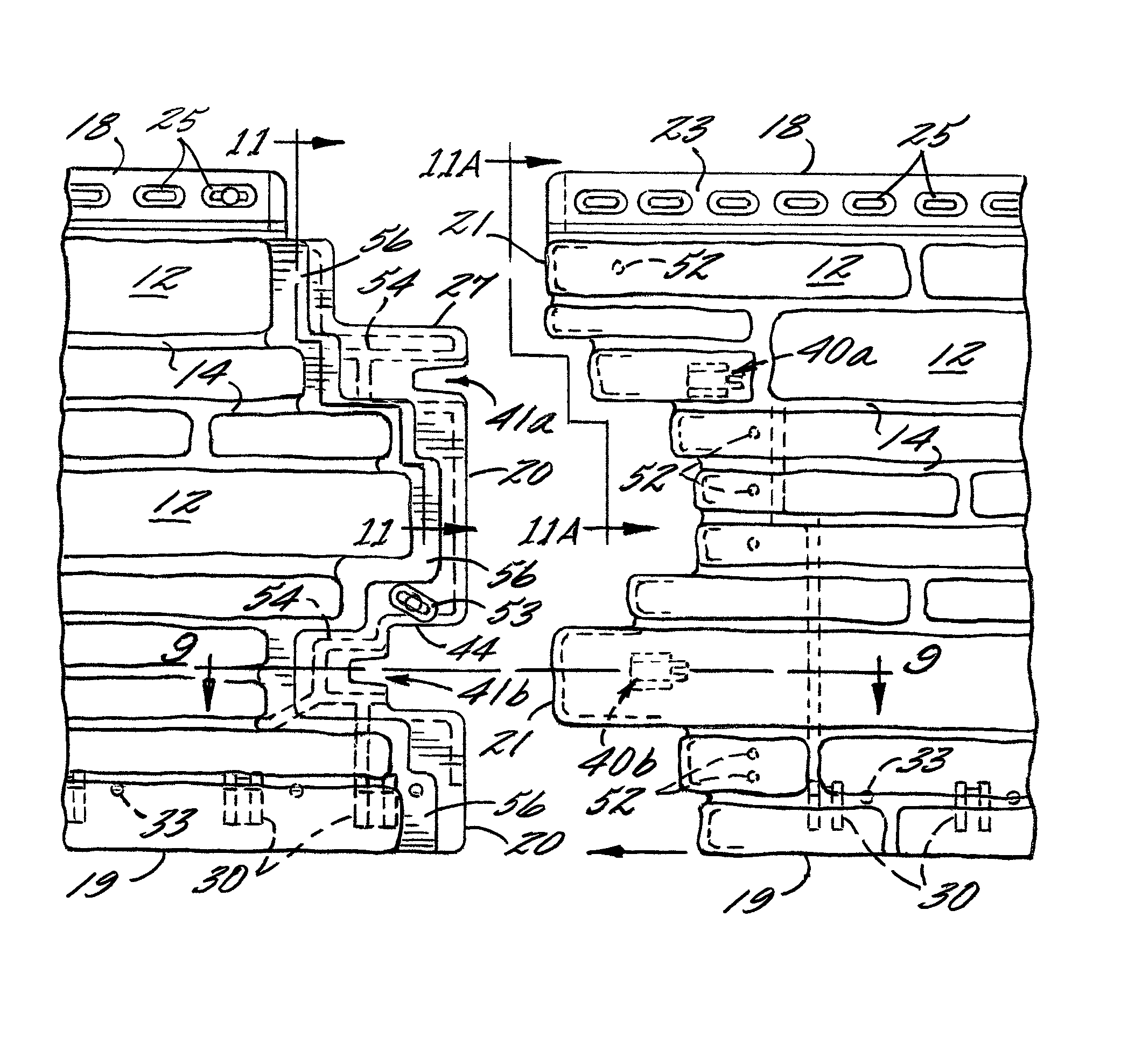
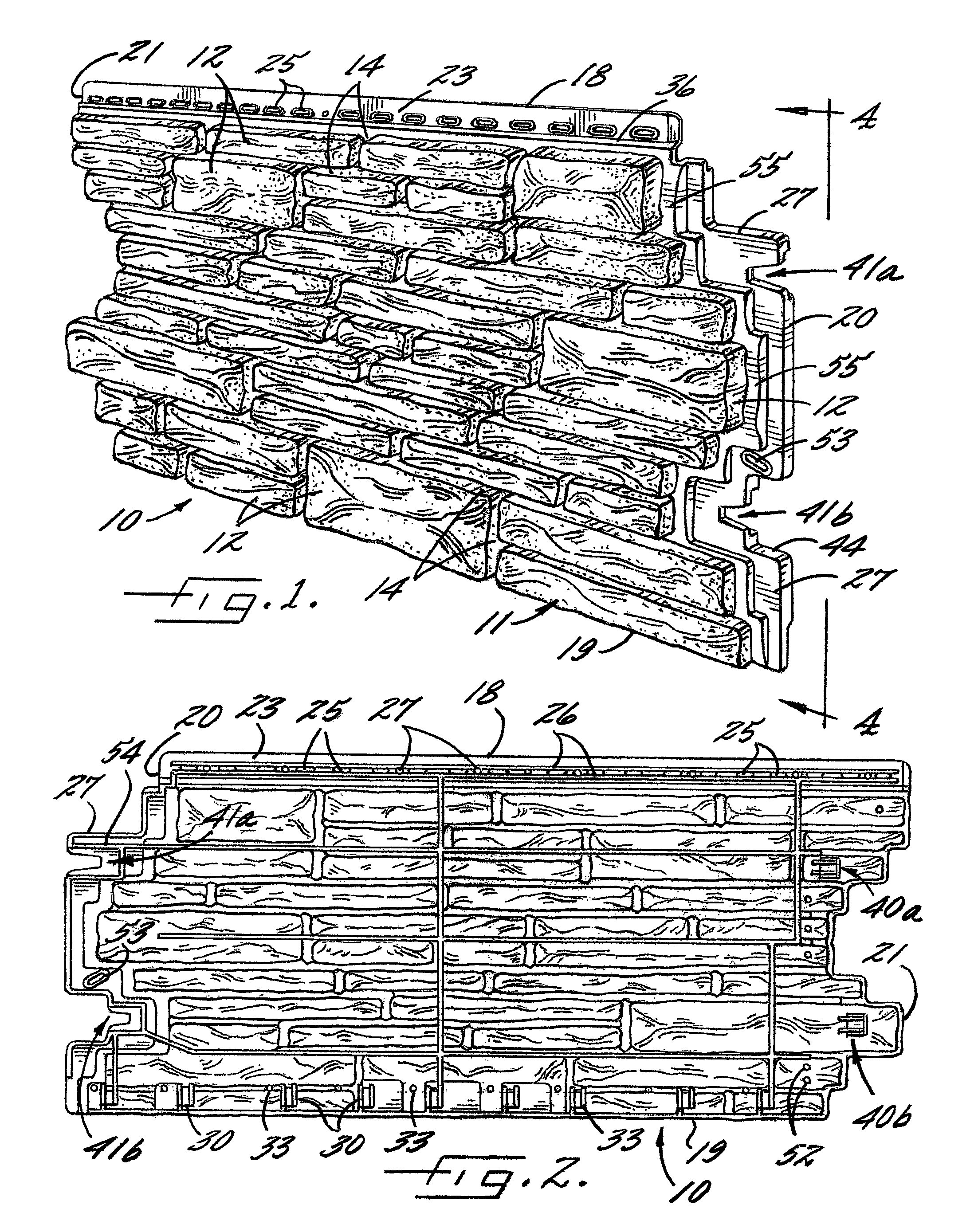
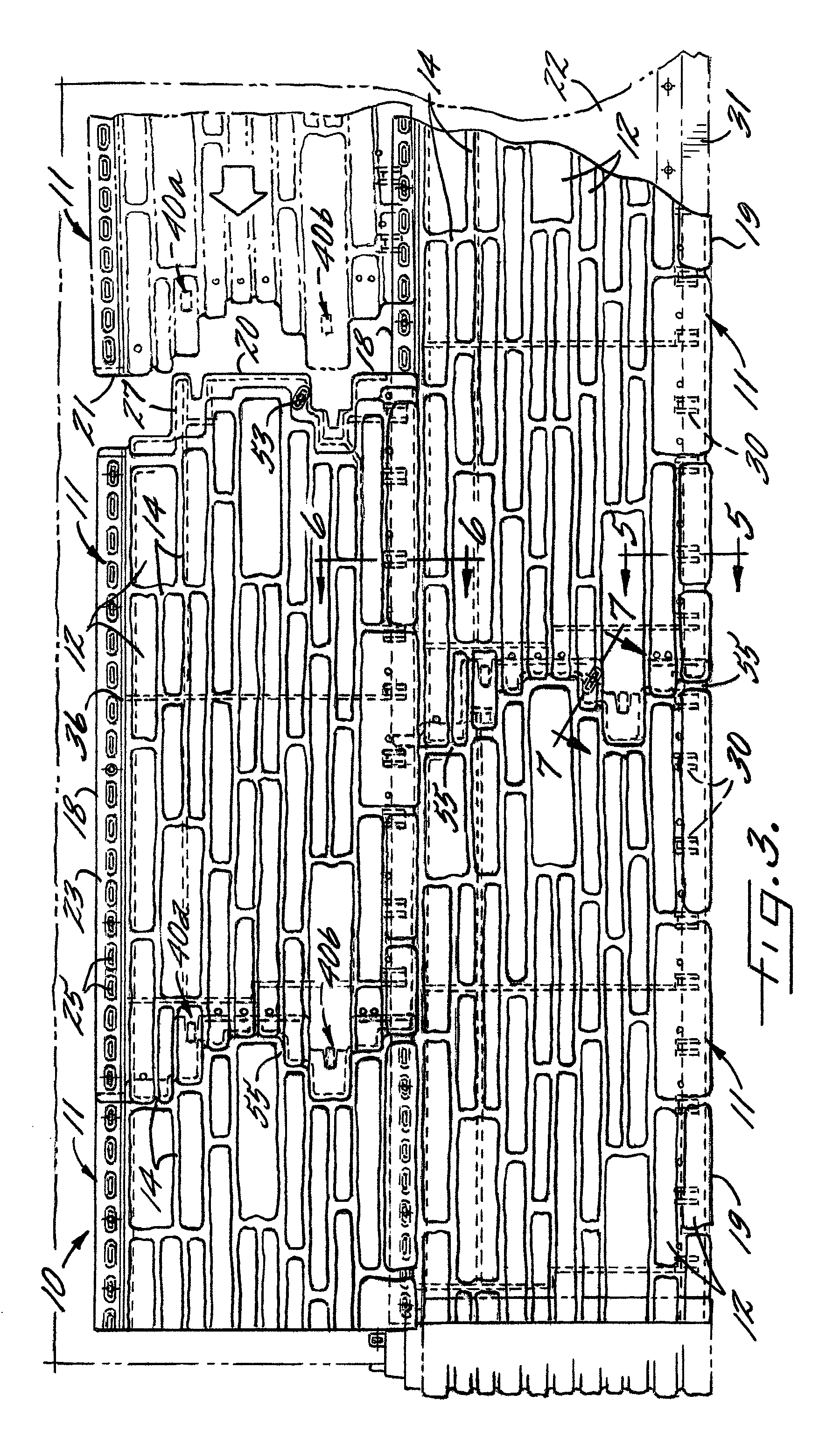
[0029]Referring now more particularly to the drawings, there is shown an illustrative wall covering 10 comprising a plurality of panels 11 in accordance with the invention. The panels 11, which preferably are molded of thermoplastic material, are formed with a simulated stone and mortar design, typical of hand-laid stone masonry. The simulated stone 12 in this case is generally disposed in a plurality of parallel horizontal rows with the stones 12 being isolated from each other by simulated lines of mortar 14. The stones 12 protrude outwardly of the mortar lines 14, typical of hand-laid stone, and some of the simulated stones 12 in this instance have a width (i.e. a vertical dimension as viewed in FIG. 1), greater than other of the stones in the row. The simulated stone 12 has irregular outer surfaces consistent with natural stone, and the mortar lines 14 also have a waving, or undulating, non-planar naturally appearing outer surface configuration. While the invention has particular...


PUM


Abstract

A wall covering comprising a plurality of panels each formed with a plurality of horizontal rows of simulated building elements, such as hand laid stone separated by simulated lines of mortar. The panels have side marginal edge regions formed with hooks and side opening slots that are interengageable as an incident to relative lateral movement of the side marginal edge regions during installation, with the rows of simulated building elements in one panel, being drawn into aligned and predetermined spaced relation to the rows of building elements and adjacently mounted panel. The underlying side marginal edge region of each panel is formed with a non-planar undulating surface similar to the mortar lines throughout the panel, and the overlying side marginal edge region of each panel further is formed with a complementary undulating surface for tight mounted positioning onto the undulating surface of the underlying side marginal edge region.

Description

FIELD OF THE INVENTION[0001]The present invention relates generally to wall and roof coverings primarily intended for outdoor usage, and more particularly, to wall coverings comprised of relatively large panels which each are molded or otherwise formed with simulated building elements, and particularly building elements in the form of simulated hand laid masonry, such as stone or brick.BACKGROUND OF THE INVENTION[0002]Various synthetic roof and wall coverings are known, such as those formed of elongated thermoplastic wall panels that are nailed or screwed to a wall or support surface in horizontal courses or rows in partially overlapping relation to each other so as to provide a substantially water repellant, protective layer over the support surface. Such panels, which usually are identically molded, commonly are formed with a plurality of horizontal rows of simulated building elements. Since the panels are identically molded, a panel-to-panel identity can be easily noticed if the ...

Claims


Application Information

Patent Timeline
Patent Type & Authority Patents(United States)
IPC IPC(8): E04D1/00
CPCE04F13/0864E04F13/185
Inventor SCHWARZ, STEFAN HELMUTTRABUE, ROBERT
Owner NOVIK INC
Why Eureka
Try Eureka