Apparatus for exercising a force on a load

a technology for a load and an apparatus, applied in the direction of mechanical apparatus, machine supports, wound springs, etc., can solve the problems of occupying a large space, relatively expensive springs compared to standard springs,

Active Publication Date: 2012-04-10
ANCHIS TECH
View PDF15 Cites 8 Cited by
  • Summary
  • Abstract
  • Description
  • Claims
  • Application Information

AI Technical Summary

Benefits of technology

[0016]As a result, the load is very lightly adjustable from any position. An important advantage of the invention is the possibility of saving a considerable amount of space, thereby enlarging the area of application of the apparatus according to the invention with, for example, completely new applications such as balancing kitchen cupboards and drawers in the vertical direction, and applications known from time immemorial like those shown, for example, in GB-A-4 89 547.
is the possibility of saving a considerable amount of space, thereby enlarging the area of application of the apparatus according to the invention with, for example, completely new applications such as balancing kitchen cupboards and drawers in the vertical direction, and applications known from time immemorial like those shown, for example, in GB-A-4 89 547.

Problems solved by technology

Such springs are relatively expensive compared with standard springs, whose spring force is proportional to the extension of the spring.
A further drawback of the apparatus known from the British patent specification GB-A-489 547 is that it takes up a rather large amount of space owing to the horizontally oriented springs requiring sufficient extension space.

Method used


Image

  • Apparatus for exercising a force on a load
  • Apparatus for exercising a force on a load
  • Apparatus for exercising a force on a load

Examples


Embodiment Construction

[0021]With respect to design, it may be advantageous for a linear characteristic to be used for the predetermined characteristic of the force path diagram of the coupling in combination with the second spring system.

[0022]It is generally desirable to provide the apparatus with a lock, which may be activated before an adjustment is made to the load. After the load adjustment the lock may be released again.

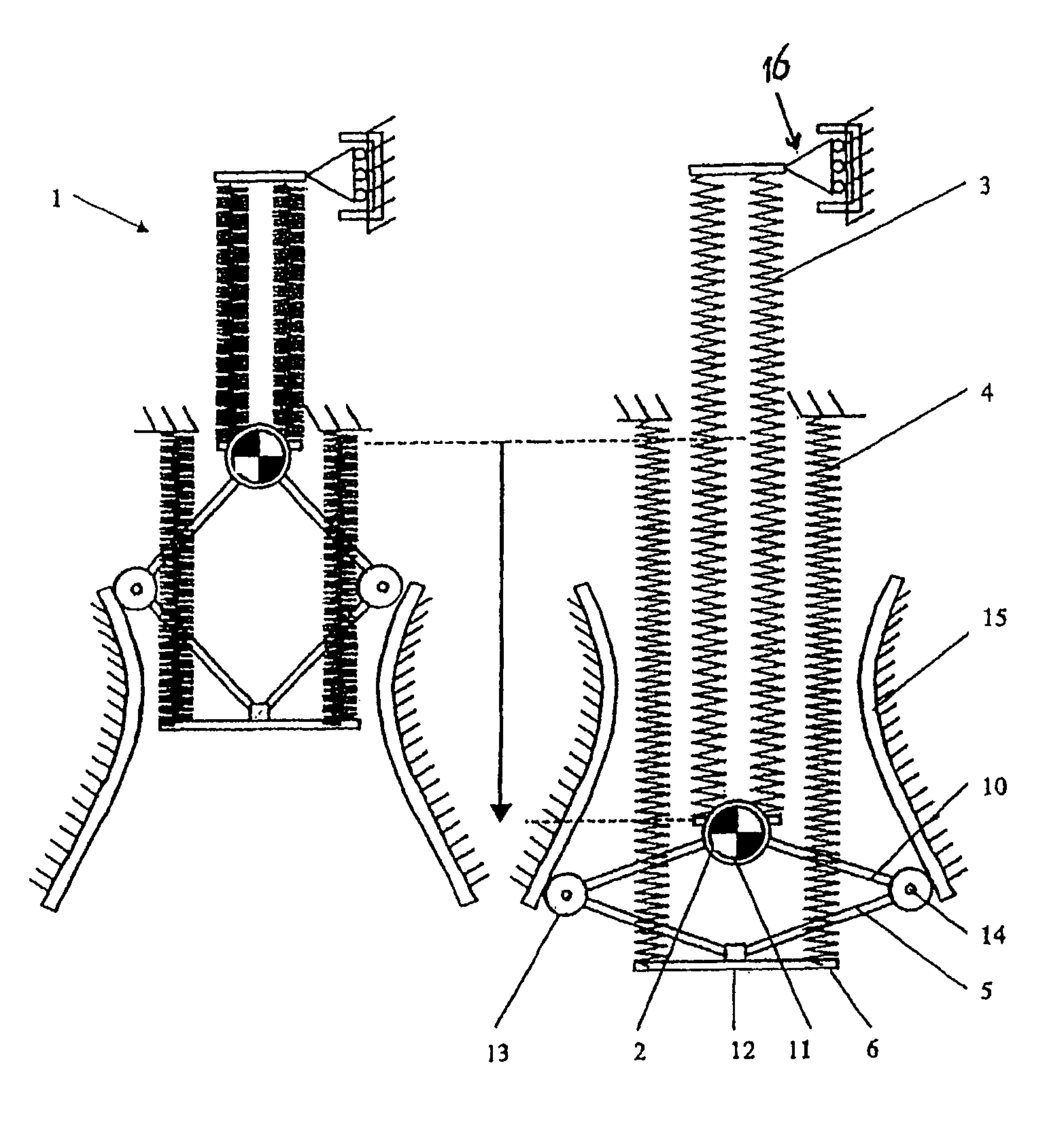
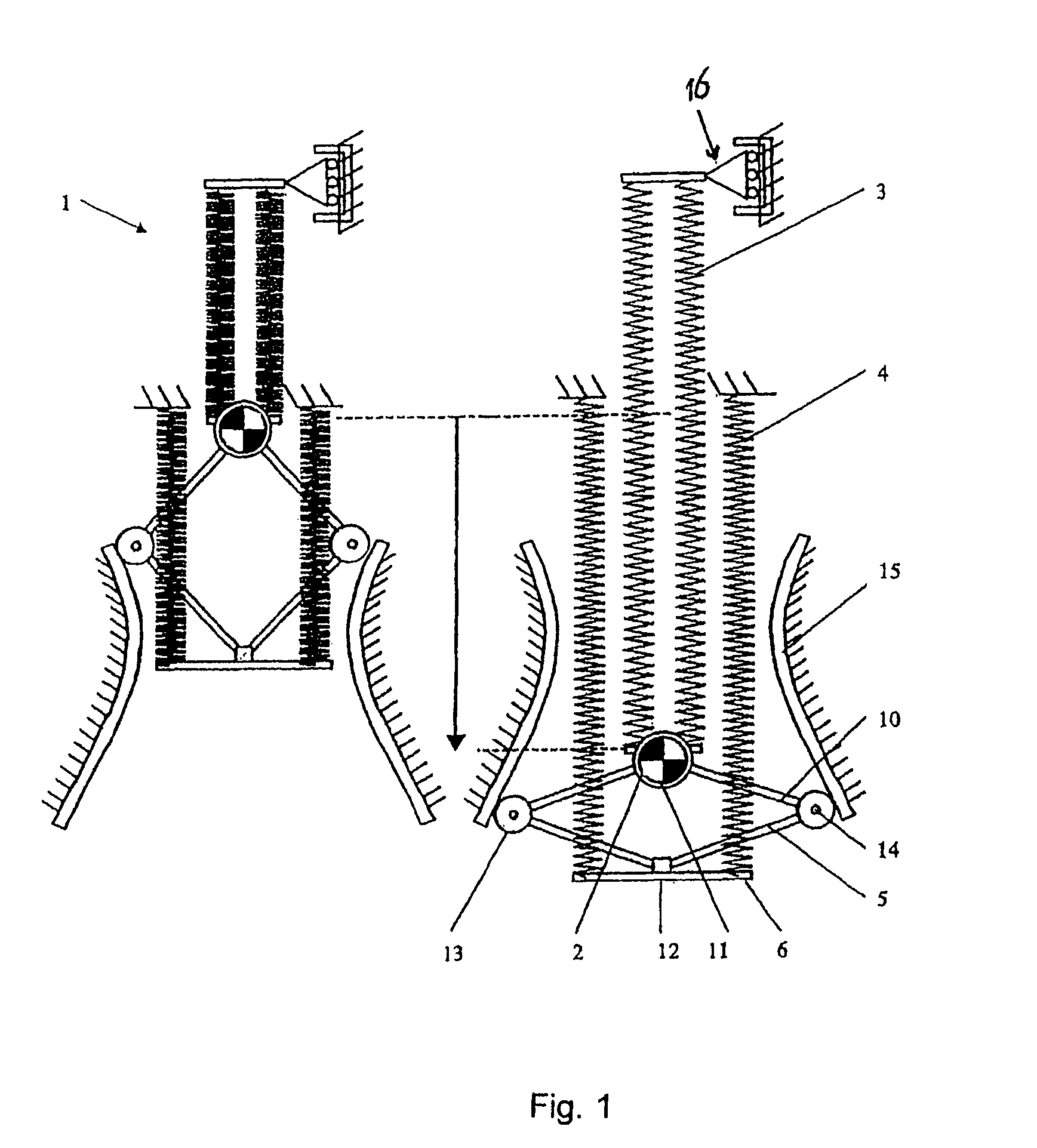
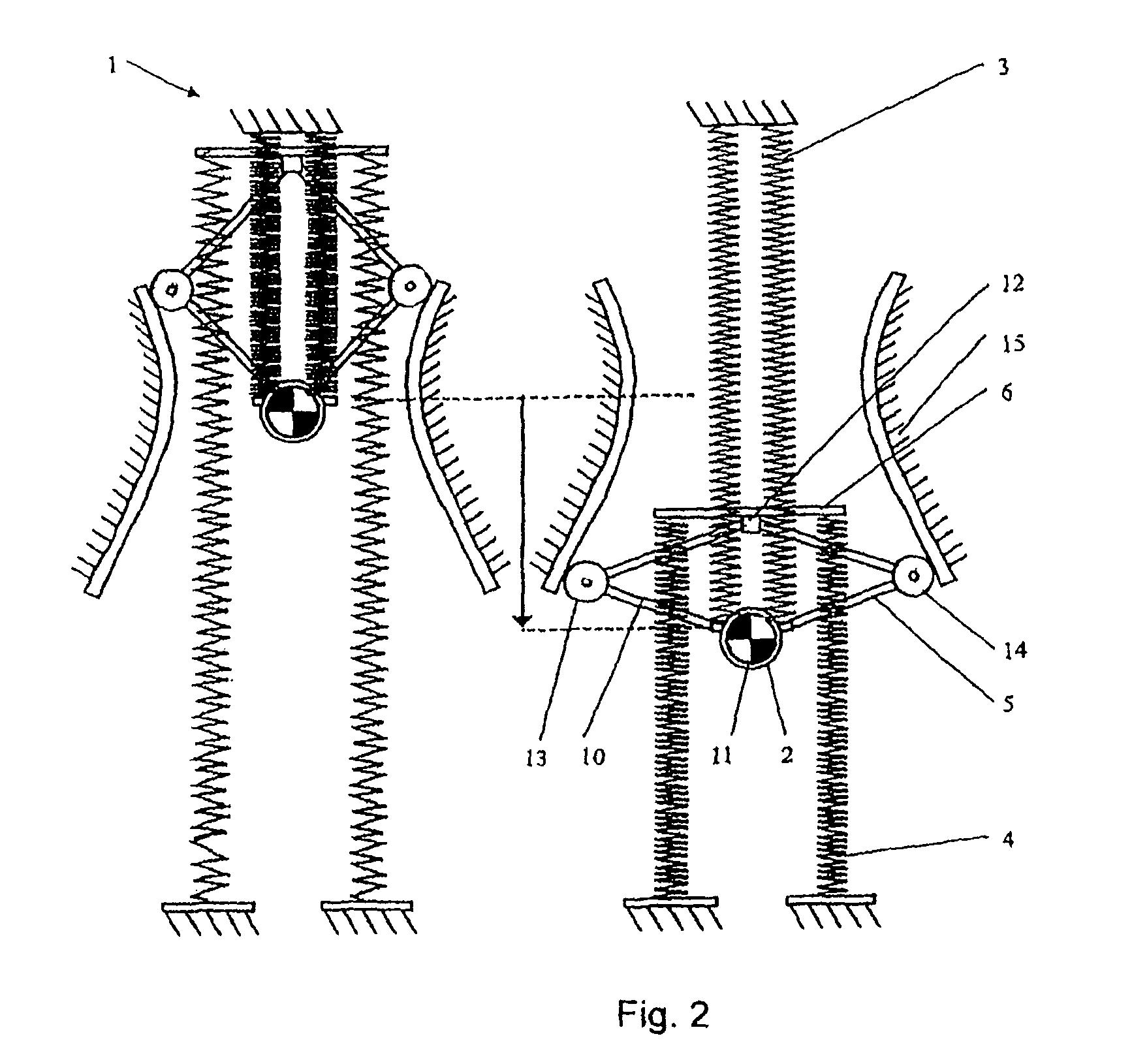
[0023]An important advantage of the apparatus according to the invention is that the first spring system and the second spring system may comprise parallel oriented springs. It is owing to this aspect in particular that the invention provides such a substantial saving in space.

[0024]The advantage of this embodiment wherein a parallelogram construction is used as the adjusting device, is that standard springs can be used.

[0025]With all the possible embodiments of the apparatus according to the invention it is an advantage for the first spring system and / or the second spring system to...


PUM


Abstract

An apparatus for exerting a force on a load, comprising at least a first spring system and a second spring system, which two spring systems are coupled with the load and produce forces that are applied to the load, wherein an adjusting device is provided coupled with the load, which is equipped with at least one coupling with which the first spring system and / or the second spring system are / is coupled, and which adjusting device is designed for moving the coupling subject to an adjustment of the load, wherein the first spring system has a linear spring characteristic and is coupled with the load, and wherein the second spring system is coupled with the coupling at a side of the coupling removed from the load, and wherein the coupling is designed for adjusting the second spring system subject to a predetermined spring characteristic of the second spring system such that, at the side of the load, the combination of the coupling with the second spring system possesses a force path diagram having a linear characteristic.

Description

CROSS-REFERENCE TO RELATED APPLICATIONS[0001]This application is a continuation application of International Patent Application Serial No. PCT / NL2008 / 050802, entitled “Apparatus for Exercising a Force on a Load”, to Technische Universiteit Delft and InteSpring Holding B.V., filed on Dec. 16, 2008, which is a continuation of Netherlands Patent Application Serial No. 2001125, entitled “Apparatus for Exercising a Force on a Load”, to Technische Universiteit Delft and InteSpring Holding B.V., filed on Dec. 21, 2007, and the specification and claims thereof are incorporated herein by reference.STATEMENT REGARDING FEDERALLY SPONSORED RESEARCH OR DEVELOPMENT[0002]Not Applicable.INCORPORATION BY REFERENCE OF MATERIAL SUBMITTED ON A COMPACT DISC[0003]Not Applicable.COPYRIGHTED MATERIAL[0004]Not Applicable.BACKGROUND OF THE INVENTION[0005]1. Field of the Invention (Technical Field)[0006]The present invention relates to an apparatus for exerting a force on a load, comprising at least a first s...

Claims


Application Information

Patent Timeline
Patent Type & Authority Patents(United States)
IPC IPC(8): F16M1/00
CPCF16M11/04F16M11/046F16M11/24F16M11/38F16M11/18F16M2200/047
Inventor WISSE, BOUDEWIJN MARTINBARENTS, ROGIERVAN DORSSER, WOUTER DIRKHERDER, JUSTUS LAURENS
Owner ANCHIS TECH
Why Eureka
Try Eureka