
Display apparatus and light control method of the same

a technology of display apparatus and light control method, which is applied in the direction of printers, cameras, instruments, etc., can solve the problem of inability to precisely sense the brightness of light, and achieve the effect of preventing the quantity of light from decreasing and preventing the brightness of an image from decreasing

Inactive Publication Date: 2012-04-10
SAMSUNG ELECTRONICS CO LTD
View PDF21 Cites 10 Cited by
  • Summary
  • Abstract
  • Description
  • Claims
  • Application Information

AI Technical Summary

Benefits of technology

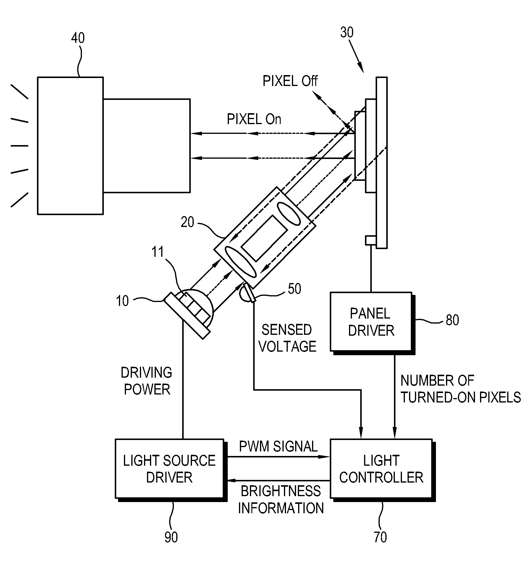
The present invention provides a display apparatus and a light control method that prevents the brightness of an image from decreasing and accurately senses the brightness of light. This is achieved by providing a display panel, a light source unit, an illumination unit to illuminate the display panel with light emitted from the light source unit, and a projection unit to project the light from the display panel in a predetermined direction. A light sensor is provided between the light source unit and the illumination unit to correct the brightness of the light reflected from the display panel to the illumination unit. The light controller adjusts at least one of a white balance and a color temperature of the light based on the brightness of the light sensed by the light sensor and the brightness of the light reflected from the display panel to the illumination unit. This invention improves the display quality of the display apparatus and enhances the user experience.

Problems solved by technology

However, in this case, the light emitted from the light source unit to the pixel elements of the display device via the illumination assembly is reflectively returned to the illumination assembly, so that the brightness of the light cannot be precisely sensed.

Method used


Image

  • Display apparatus and light control method of the same
  • Display apparatus and light control method of the same
  • Display apparatus and light control method of the same

Examples


Embodiment Construction

[0029]Below, embodiments of the present invention will be described in detail with reference to accompanying drawings so as to be easily realized by a person having ordinary knowledge in the art. The present invention may be embodied in various forms without being limited to the embodiments set forth herein. Descriptions of well-known parts are omitted for clarity, and like reference numerals refer to like elements throughout.

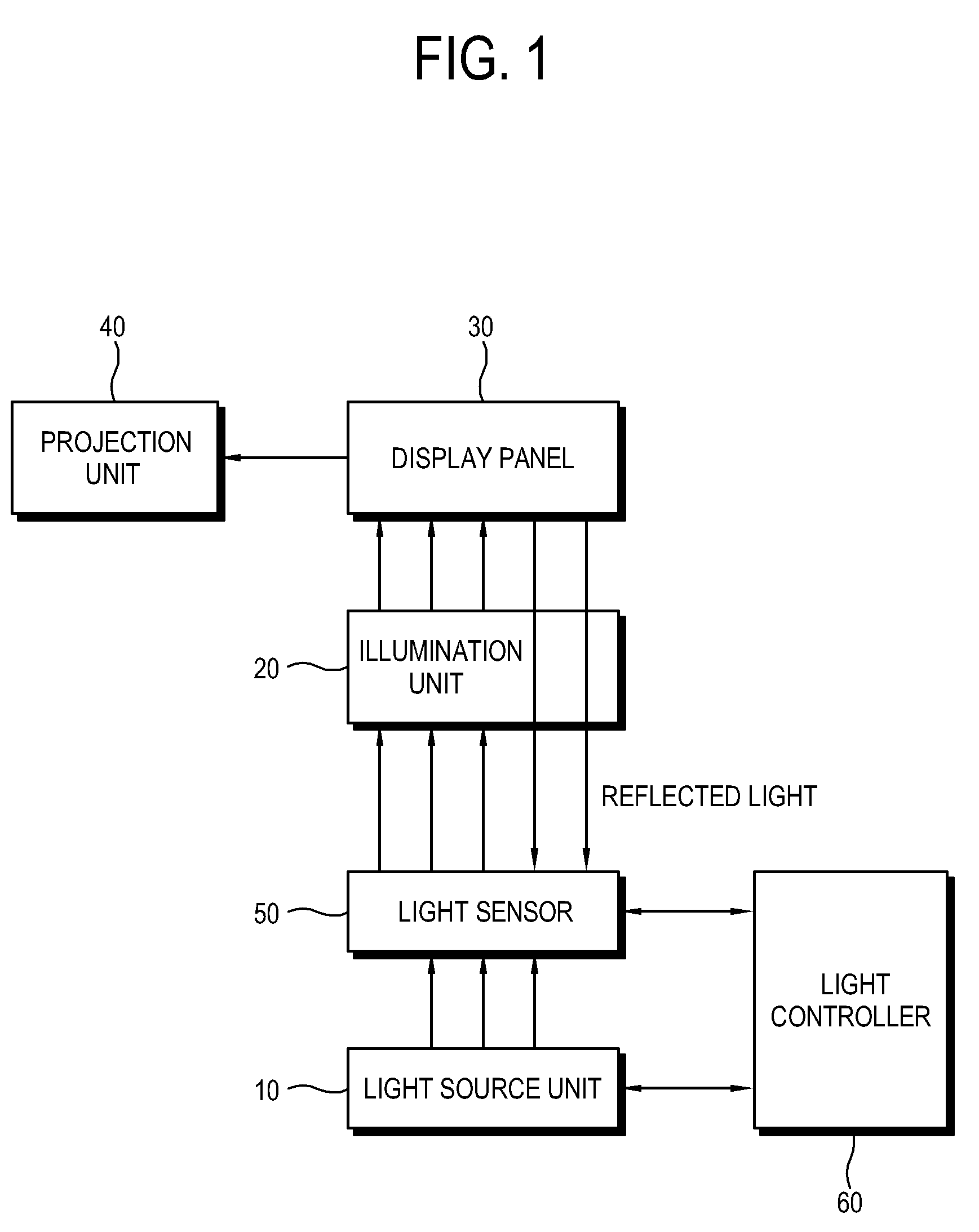
[0030]FIG. 1 is a control block diagram of a display apparatus according to a first exemplary embodiment of the present invention.

[0031]As shown therein, the display apparatus includes a light source unit 10, an illumination unit 20, a display panel 30, a projection unit 40, a light sensor 50, and a light controller 60. In this embodiment, the display apparatus may be achieved by a projection system that enlarges and projects light from the display panel 30 to a region such as a screen where an image is displayed.

[0032]The light source unit 10 emits light to th...


PUM


Abstract

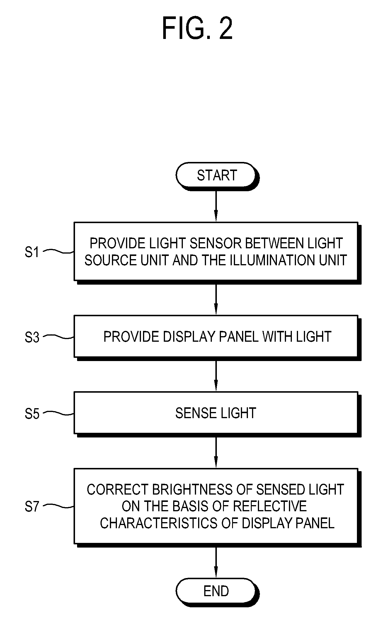
Disclosed are a display apparatus and a light control method thereof, in which the display apparatus including a display panel, a light source unit, an illumination unit to illuminate the display panel with light emitted from the light source unit, and a projection unit to project the light from the display panel in a predetermined direction includes: a light sensor which is provided between the light source unit and the illumination unit; and a light controller which corrects brightness of light sensed by the light sensor on the basis of reflective characteristics of the display panel. With this configuration, the quantity of light is prevented from decreasing so as to prevent the brightness of an image from decreasing.

Description

CROSS-REFERENCE TO RELATED APPLICATION[0001]This application claims priority from Korean Patent Application No. 10-2008-0031221, filed on Apr. 3, 2008 in the Korean Intellectual Property Office, the disclosure of which is incorporated herein by reference.BACKGROUND OF INVENTION[0002]1. Field of Invention[0003]Apparatuses and methods consistent with the present invention relate to a display apparatus and a light control method of the same, and more particularly to a display apparatus having an optical system to enlarge and project light and a light control method of the same.[0004]2. Description of the Related Art[0005]Among display apparatuses, a projection system enlarges and projects an image formed by a display device to a screen, thereby providing a large-sized image. The projection system includes a light source unit to emit light, an illumination assembly to condense the light emitted from the light source unit, a display device to form an image with the light received from th...

Claims


Application Information

Patent Timeline
Patent Type & Authority Patents(United States)
IPC IPC(8): G03B21/20
CPCG03B21/00H04N9/3111H04N9/3197H04N9/3194H04N9/312G03B21/005H04N5/74H04N9/31
Inventor CHO, BONG-HWAN
Owner SAMSUNG ELECTRONICS CO LTD
Learn More