Method and apparatus for network tree management

a network tree and tree technology, applied in the direction of electrical equipment, digital transmission, data switching networks, etc., can solve the problems of not being able to achieve the effect not being able to achieve the effect of achieving the effect of improving the recovery tim

Active Publication Date: 2012-04-10
TELEFON AB LM ERICSSON (PUBL)
View PDF10 Cites 7 Cited by
  • Summary
  • Abstract
  • Description
  • Claims
  • Application Information

AI Technical Summary

Benefits of technology

[0012]To address the above-discussed deficiencies of the prior art, it is a primary object of the present invention to provide a method and arrangement for configuring the active topology of a computer network, for example an Ethernet LAN. It is a further object of the invention to apply an improved link state approach to network tree management, the improved link state approach having, among other things, an advantageous architecture and an improved recovery time as compared with conventional approaches.
[0013]In one aspect, the invention is a method for configuring a network, such as an Ethernet LAN, for efficient forwarding of data traffic, including collecting neighbor information, generating and distributing link state advertisements, populating a topology database for the network, and calculating in a root bridge the port states for each bridge in a tree using from the topology database. The method may further include advertising the tree by selectively distributing tree advertisement messages, receiving tree advertisement messages in bridges of the network, and configuring the ports of each bridge according to the advertisement message. The method may also further include the feature of recognizing, in a network bridge that a link state advertisement has already been processed, and to discard rather than forward them. In this way, a protocol for links states STP is defined that allows the application of flexible sets of routing objectives.
[0014]In another aspect, the present invention is a network comprising at least one root bridge, wherein the root bridge is remotely sets the port states of at least one other network bridge. In a preferred embodiment, the active network topology is calculated at the root bridge and imposed on all the other network bridges. A root bridge therefore is arranged to build a topology database and use the topology data base to calculate a spanning tree for the network. The root bridge is further arranged to generate and distribute tree advertisement messages that describe the tree for non-root bridges. Non-root bridges are arranged to receive the tree advertisement messages and process them. The non-root bridges are also arranged to configure their ports according to the description in the tree advertisement message, and to selectively forward the tree advertisement messages in the direction of leaf bridges. Non-root bridges may also be arranged to modify the tree description in the tree advertisement message prior to forwarding them to other bridges. In this manner, problems due to any potential inconsistency in link state databases may be mitigated or eliminated entirely, as the time needed to synchronize databases following a failure is eliminated. In some embodiments, the use of alternate or backup ports is implemented when a failure condition is detected.

Problems solved by technology

Without some governing protocol, however, it is possible that frames of data might inadvertently be sent from bridge to bridge, eventually looping back to a previously-visited bridge from which they are re-sent back into the same loop.
As should be apparent, this is not a desirable phenomenon and techniques have evolved for avoiding this looping problem.
Most networks are subject to change, however, and occasionally encounter break downs or congestion in components and links.
A static routing system is therefore not the best solution.
It is therefore possible, or even likely, that the topology is not optimal.
The distance vector approach is also less efficient at fault handling, that is at recovering from a failure occurring somewhere in the network.
This is not a detriment in and of itself, but it may produce long unavailable periods resulting in at least transient loops.
Another complication is that Ethernet frames do not include a TTL (time to live) field (as does an IP packet) so transient loops may be problematic when changes in active topology are occurring.
Of course, bridges that notice the topology is changing could simply stop forwarding data frames until a new topology is calculated, but this procedure slows down the recovery significantly.

Method used


Image

  • Method and apparatus for network tree management
  • Method and apparatus for network tree management
  • Method and apparatus for network tree management

Examples


Embodiment Construction

[0035]FIGS. 1 through 16, discussed herein, and the various embodiments used to describe the principles of the present invention in this patent document are by way of illustration only and should not be construed in any way to limit the scope of the invention. Those skilled in the art will understand that the principles of the present invention may be implemented in any suitably arranged computer network.

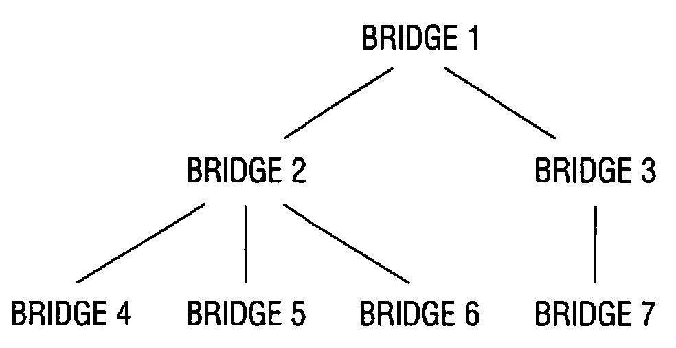
[0036]The present invention is directed to a new approach to facilitating the management of data traffic flow in a network, such as an Ethernet LAN (local area network), using a spanning tree active topology. FIG. 16 is a flow diagram illustrating a method 20 of facilitating data traffic flow according to an embodiment of the present invention. At START it is assumed that a network operable to communicate data via a plurality of bridges has been formed, such as the one shown in FIG. 15. The network is, for example, an Ethernet LAN network operable according to the IEEE 802 family of...


PUM


Abstract

There is disclosed a manner of managing the active topology, that is the scheme for forwarding data, in a computer network such as an Ethernet local area network. A root bridge is selected from a plurality of bridges in the network; the root bridge calculating at least one spanning tree from a topology database that has been populated by bridge neighbor information gleaned from link state advertising messages. The root bridge may also calculate an alternate topology for implementation in the event a failure condition that affects the primary spanning tree is detected. The root bridge then advertises the spanning tree and remotely configures the port states of the bridges in the spanning tree through tree advertising messages that the bridges are arranged to process and set their ports accordingly.

Description

RELATED APPLICATION AND CLAIM OF PRIORITY[0001]This application is related to and claims benefit of the filing date of U.S. Provisional Patent Application No. 60 / 885,667 filed Jan. 19, 2007, which is entirely incorporated by reference herein.TECHNICAL FIELD OF THE INVENTION[0002]The present invention is directed, in general, to controlling data traffic in computer networks and, more specifically, to a method and system for tree management in Ethernets and similar networks using link state principles.BACKGROUND OF THE INVENTION[0003]Computers, broadly speaking, are electronic machines capable of storing and manipulating information, often called data, to useful ends. Frequently, a number of computers are connected together in such a way that they are able to send data to each other. A collection of computers so connected is often called a network, and the connector between two network nodes is referred to as a link. One type of computer network is called a LAN (local area network), a...

Claims


Application Information

Patent Timeline
Patent Type & Authority Patents(United States)
IPC IPC(8): H04L12/28H04L12/56
CPCH04L12/462H04L45/02H04L45/025H04L45/04H04L45/48H04L45/03
Inventor FARKAS, JANOSANTAL, CSABATAKACS, ATTILASALTSIDIS, PANAGIOTIS
Owner TELEFON AB LM ERICSSON (PUBL)
Why Eureka
Try Eureka