Optical system with variable field depth

a variable field depth, optical system technology, applied in the field of optical systems, can solve the problems of reducing the resolution and luminous capture of the optical system, closing the pupil,

Inactive Publication Date: 2012-04-17
UNIV DE GUANAJUATO
View PDF5 Cites 23 Cited by
  • Summary
  • Abstract
  • Description
  • Claims
  • Application Information

AI Technical Summary

Problems solved by technology

However, closing the pupil also reduces the resolution and the luminous capture of the optical system, as described in Leo Levi, Applied Optics: A Guide to Optical System Design / Volume I.

Method used


Image

  • Optical system with variable field depth
  • Optical system with variable field depth
  • Optical system with variable field depth

Examples


examples

[0035]The following is a discussion of a new optical path distribution of φ (α) that exemplifies the present invention. If selected

φ(α)=cos(πα / 2Ω)  (8)

[0036]In equation 8 the Greek letter Ω denotes (as shown above in equation 1) the upper limit of α. It should be recognized in equation 8 that the function cos (πα / 2Ω) is a symmetric function in α, so it is straightforward to verify that equation 8 complies with the condition of equation 6. Additionally, from equation 8 it is easily obtained that the optical path difference is

φ(α+υ / 2)−φ(ααυ / 2)=−[2 sen(πυ / 4Ω)] sen(πα / 2Ω)  (9)

[0037]Again, it is straightforward to verify that the result of equation 9 satisfies the condition in equation 7.

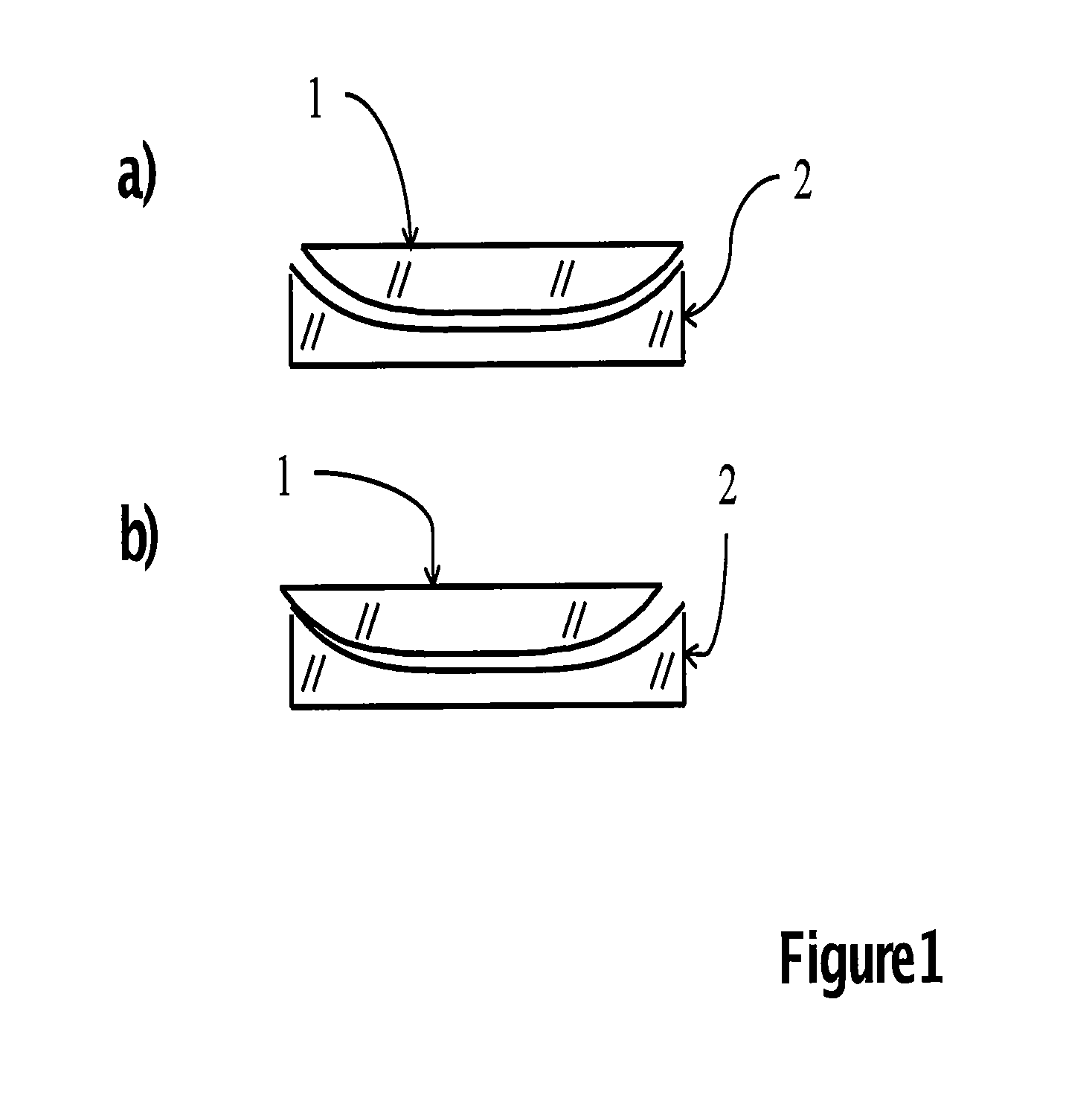
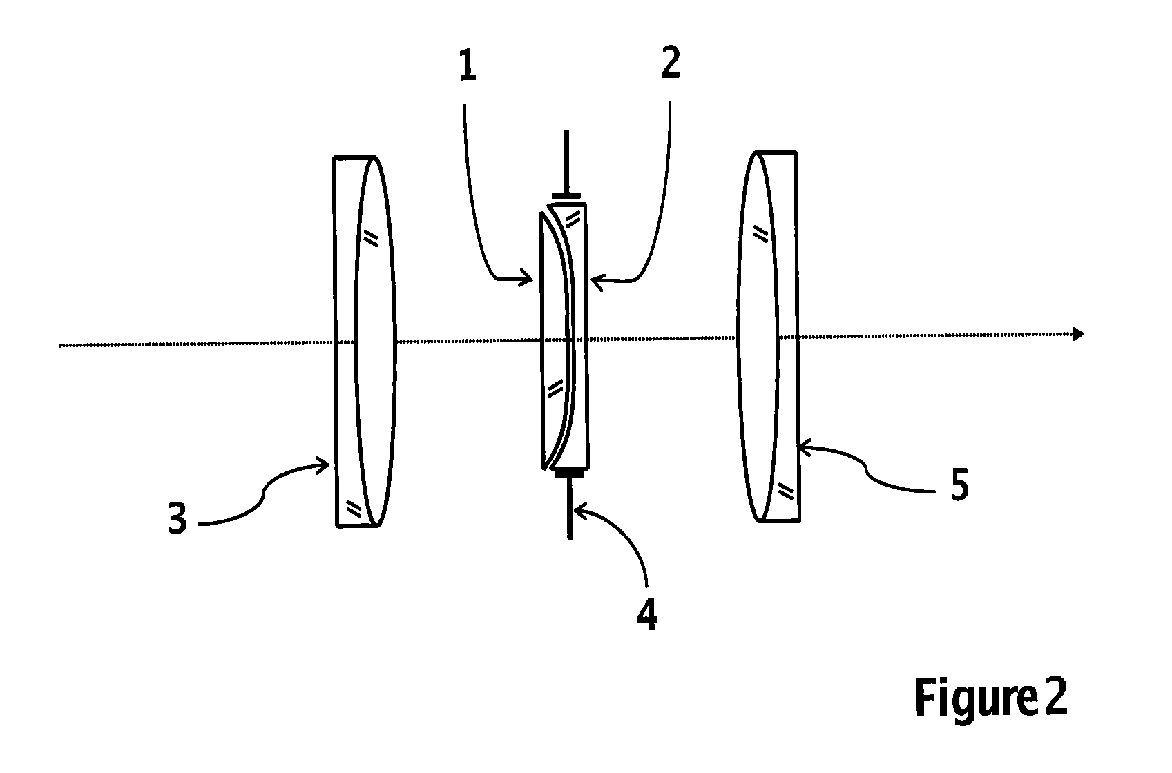
[0038]Additionally, obtained from equation 9, is that the function sin (πα / 2Ω) is amplified by the factor [2sen (πυ / 4Ω)]. The amplification factor depends only on the variable υ, which is known to represent the displacement between the two lenses in the pair used in the present invention. Thus for zero d...


PUM


Abstract

An optical lens which, in a controlled manner, and without altering either the resolution or luminous capture, helps to extend the depth of field of any other optical system. The optical lens of the present invention is composed of two optical lenses that form a pair. Each of the lenses of the pair produces a change of optical path with a symmetrical distribution. If there is no relative displacement, the lenses of the pair generate an optical path difference equal to zero. When there is relative displacement, the lenses of the pair generate a change of optical path with asymmetric distribution, which helps to extend the depth of field without reducing either the resolution or luminous capture. The optical lens of this invention, in the form of an optical pair, serves any other optical system to capture images without loss of modulation, but with attenuated modulation which can be retrieved with digital processing algorithms known in the art.

Description

CROSS-REFERENCE TO RELATED APPLICATIONS[0001]This application claims priority from Mexican Application No. MX / a / 2010 / 005782, having a filing date of May 27, 2010 with the title “Sistema Óptico Con Profundidad de Campo Variable”. The disclosure of Mexican Application No. MX / a / 2010 / 005782 is incorporated by reference herein in its entirety.BACKGROUND OF THE INVENTION[0002]It is advisable to describe an optical system that captures the image, of a three-dimensional object, as a process of transfer between planes. By using an optical system, only one plane of the object is well focalized on the plane in which the image is detected. The other planes of the object are not well focalized on the plane where the image is detected. It is common to indicate that for the other planes of the object, the optical system suffers from focalization errors.[0003]The tolerance with which the optical system is able to capture the other levels of the object, is called depth of field, which is controlled ...

Claims


Application Information

Patent Timeline
Patent Type & Authority Patents(United States)
IPC IPC(8): G02B9/00G02B9/04
CPCG02B3/0081
Inventor OJEDA CASTANEDA, JORGEAGUILERA GOMEZ, EDUARDOPLASCENCIA MORA, HECTORTORRES CISNEROS, MIGUELLEDESMA OROZCO, ELIAS RIGOBERTOMARTINEZ, ALEJANDRO LEONPACHECO SANTAMARIA, JOSE SERGIOMARTINEZ CASTRO, JUAN GERARDOSALAS SEGOVIANO, ROBERTO CARLOS
Owner UNIV DE GUANAJUATO
Why Eureka
Try Eureka