
Multi-state memory cell with asymmetric charge trapping

a memory cell and charge trapping technology, applied in the field of memory cells, can solve the problems of volatile memory devices, cell operation problems, and inability to retain data

Active Publication Date: 2006-07-04
MICRON TECH INC
View PDF110 Cites 10 Cited by
  • Summary
  • Abstract
  • Description
  • Claims
  • Application Information

AI Technical Summary

Benefits of technology

The solution enables high memory density, low power operation, and enhanced reliability through localized charge storage and improved data retention, addressing the limitations of smaller cell sizes in existing technologies.

Problems solved by technology

Some memory devices are volatile in nature and cannot retain data without an active power supply.
Smaller dimensions of many device elements may cause operational problems with the cell.
For example, the channel between the source / drain regions becomes shorter possibly causing severe short channel effects.

Method used


Image

  • Multi-state memory cell with asymmetric charge trapping
  • Multi-state memory cell with asymmetric charge trapping
  • Multi-state memory cell with asymmetric charge trapping

Examples


Embodiment Construction

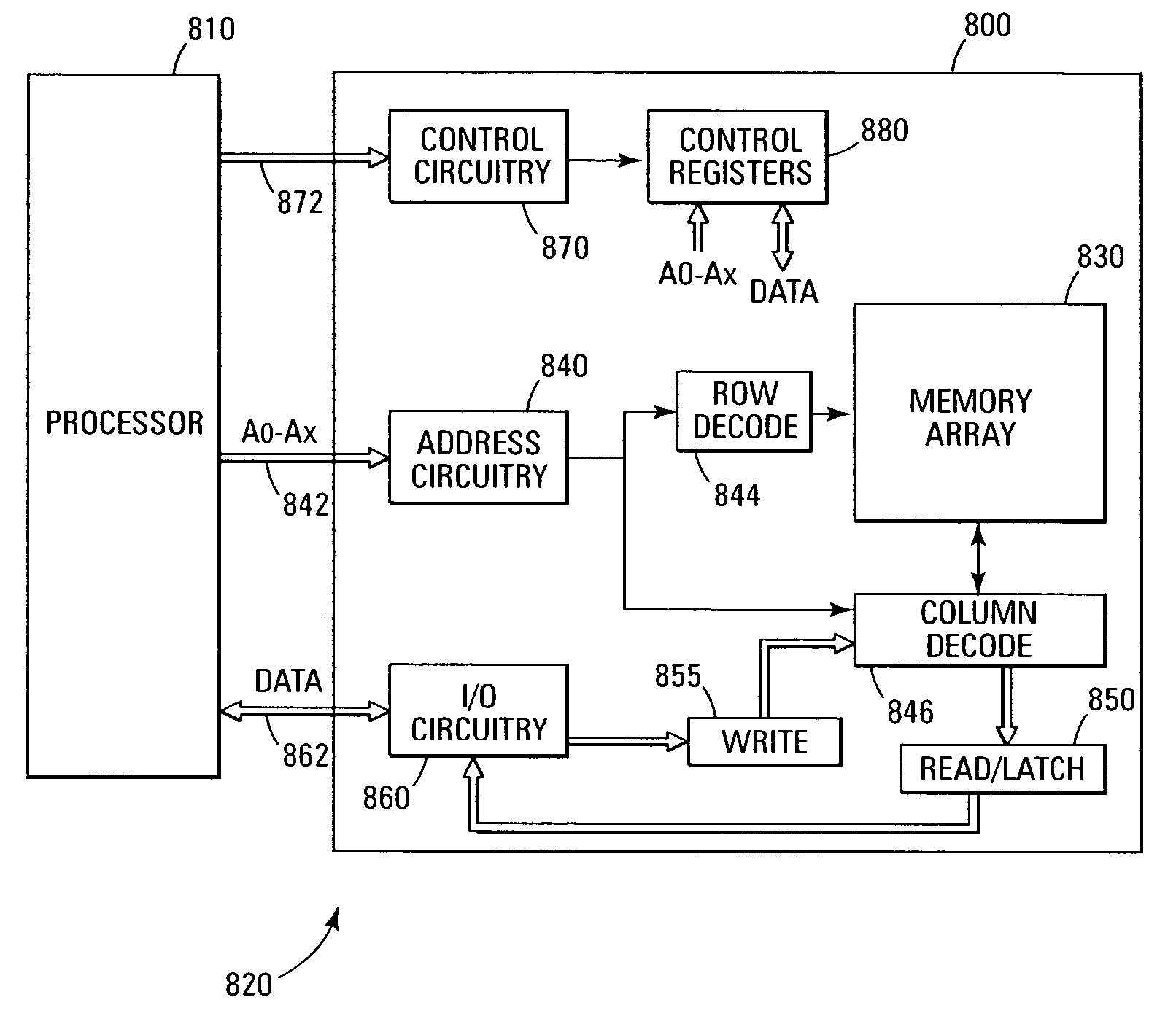
[0019]In the following detailed description of the invention, reference is made to the accompanying drawings that form a part hereof, and in which is shown, by way of illustration, specific embodiments in which the invention may be practiced. In the drawings, like numerals describe substantially similar components throughout the several views. These embodiments are described in sufficient detail to enable those skilled in the art to practice the invention. Other embodiments may be utilized and structural, logical, and electrical changes may be made without departing from the scope of the present invention. The terms wafer or substrate, used in the following description, include any base semiconductor structure. Both are to be understood as including silicon-on-sapphire (SOS) technology, silicon-on-insulator (SOI) technology, thin film transistor (TFT) technology, doped and undoped semiconductors, epitaxial layers of a silicon supported by a base semiconductor structure, as well as o...


PUM


Abstract

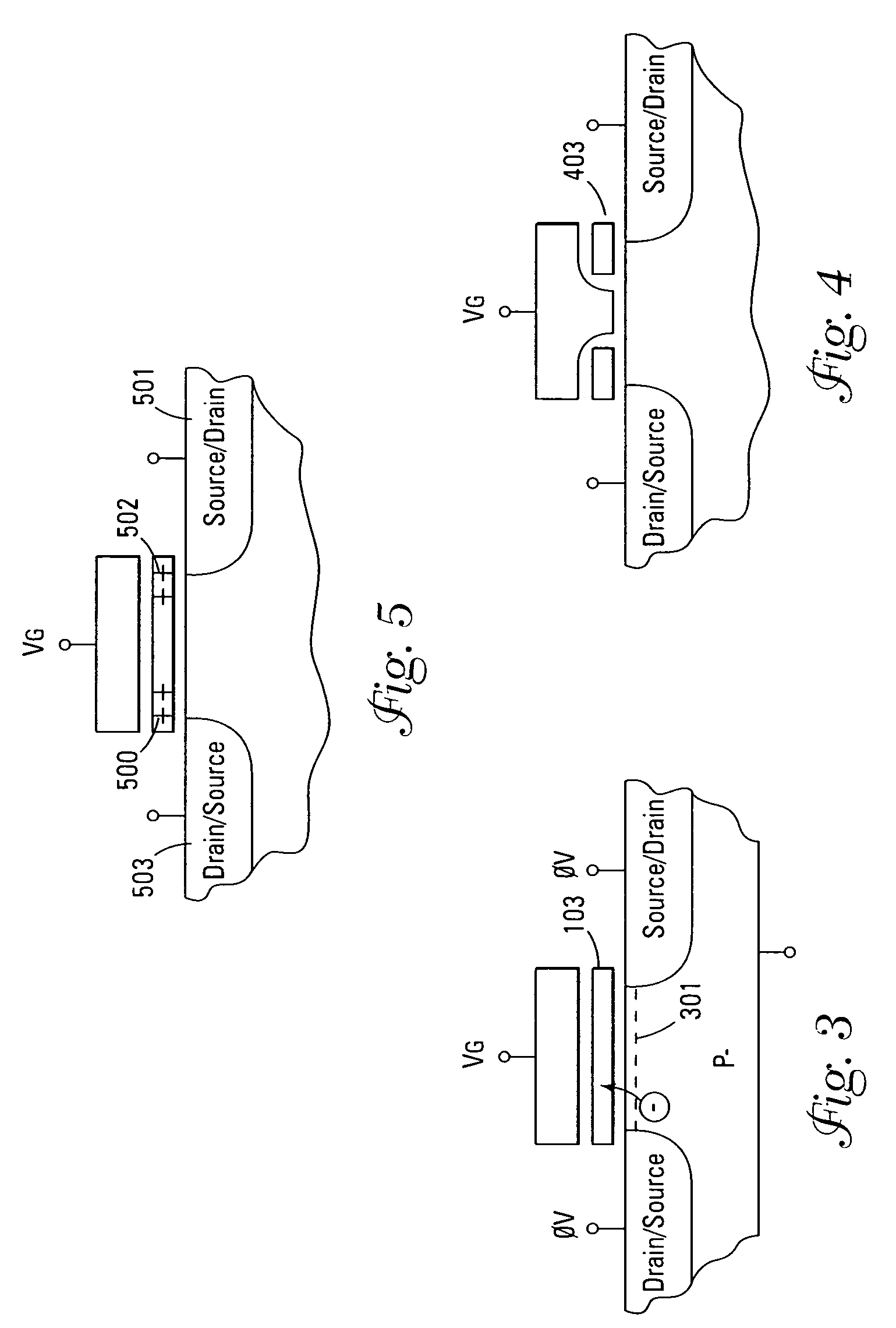
A multi-state NAND memory cell is comprised of two drain / source areas in a substrate. An oxide-nitride-oxide structure is formed above the substrate between the drain / source areas. The nitride layer acting as an asymmetric charge trapping layer. A control gate is located above the oxide-nitride-oxide structure. An asymmetrical bias on the drain / source areas causes the drain / source area with the higher voltage to inject an asymmetric distribution hole by gate induced drain leakage injection into the trapping layer substantially adjacent that drain / source area.

Description

TECHNICAL FIELD OF THE INVENTION[0001]The present invention relates generally to memory cells and in particular the present invention relates to multi-state non-volatile memory cells.BACKGROUND OF THE INVENTION[0002]Memory devices are available in a variety of styles and sizes. Some memory devices are volatile in nature and cannot retain data without an active power supply. A typical volatile memory is a DRAM which includes memory cells formed as capacitors. A charge, or lack of charge, on the capacitors indicate a binary state of data stored in the memory cell. Dynamic memory devices require more effort to retain data than non-volatile memories, but are typically faster to read and write.[0003]Non-volatile memory devices are also available in different configurations. For example, floating gate memory devices are non-volatile memories that use floating gate transistors to store data. The data is written to the memory cells by changing a threshold voltage of the transistor and is re...

Claims


Application Information

Patent Timeline
Patent Type & Authority Patents(United States)
IPC IPC(8): G11C16/04H01L29/788H01L29/792
CPCH01L29/7923H01L29/7887
Inventor PRALL, KIRK
Owner MICRON TECH INC
Learn More