

Device for expanding an exit pupil in two dimensions
a technology of two dimensions and exit pupil, which is applied in the direction of instruments, optical waveguide light guides, optics, etc., can solve the problems of limiting the size of the display incorporated in the device, the small size of the portable device, etc., and achieves the effect of facilitating the production of diffractive beam expanders, improving overall efficiency of coupling light from input grating to output grating, and improving image quality
- Summary
- Abstract
- Description
- Claims
- Application Information
AI Technical Summary
Benefits of technology
Problems solved by technology
Method used
Image

Examples
Embodiment Construction
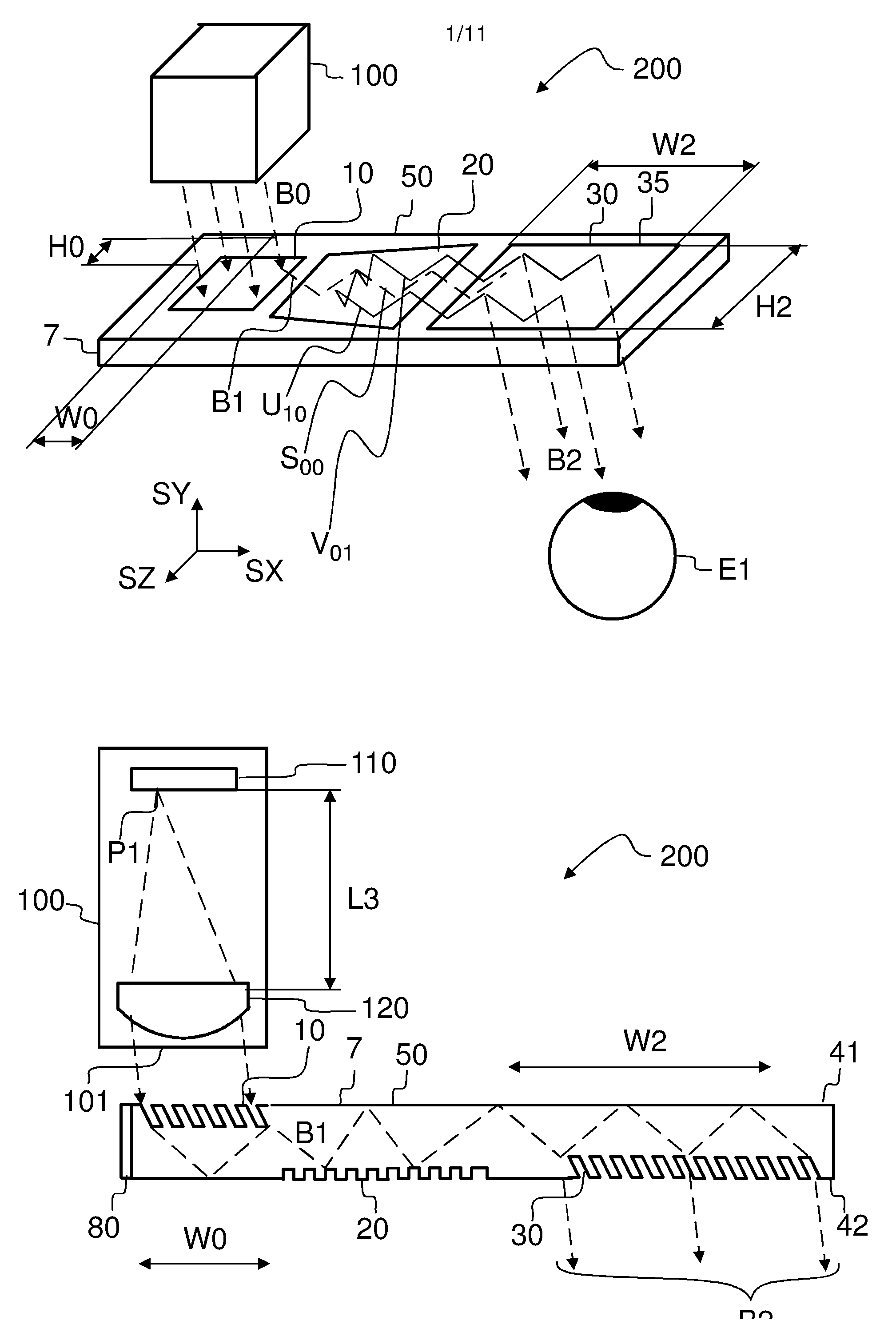
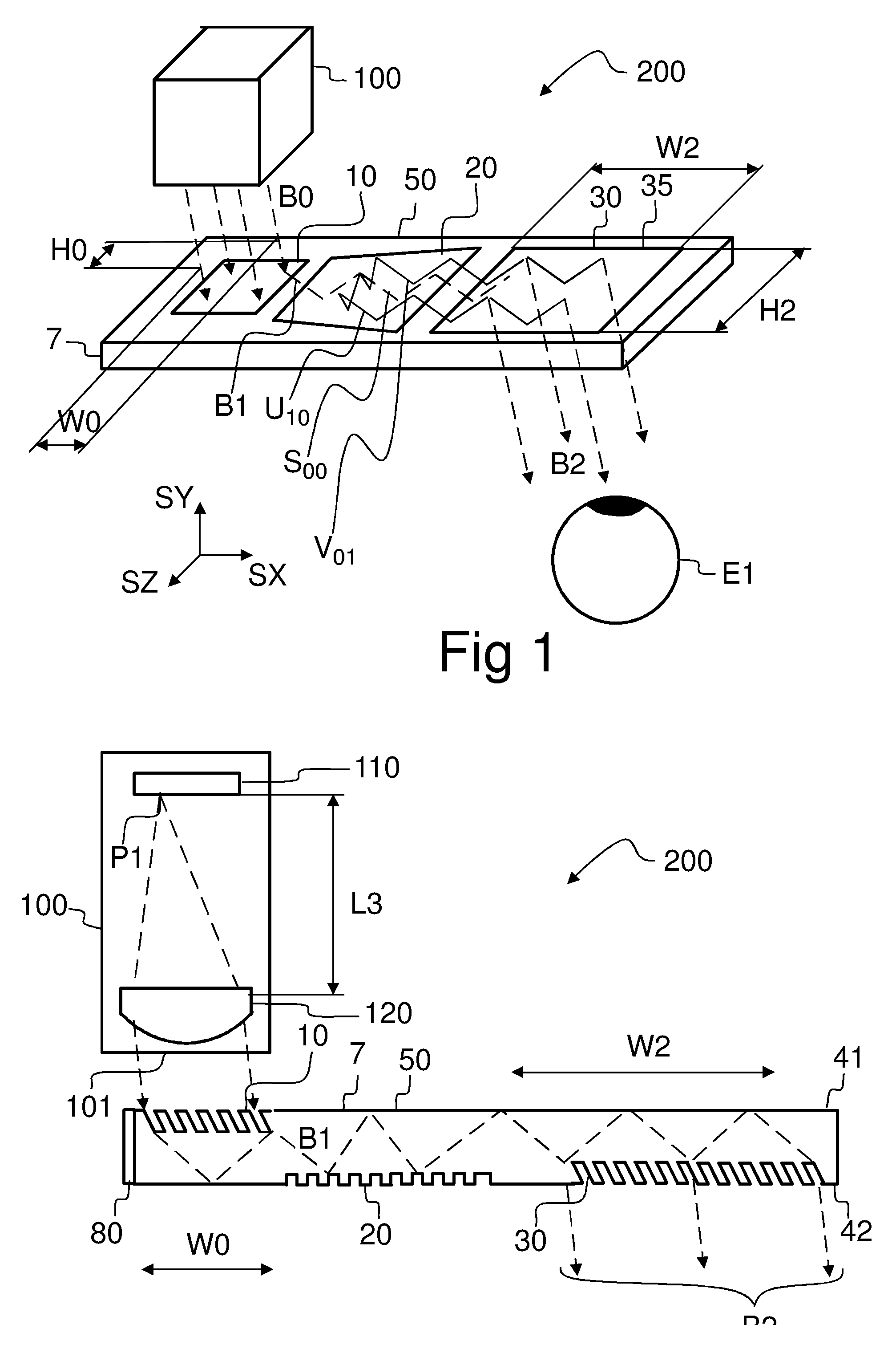
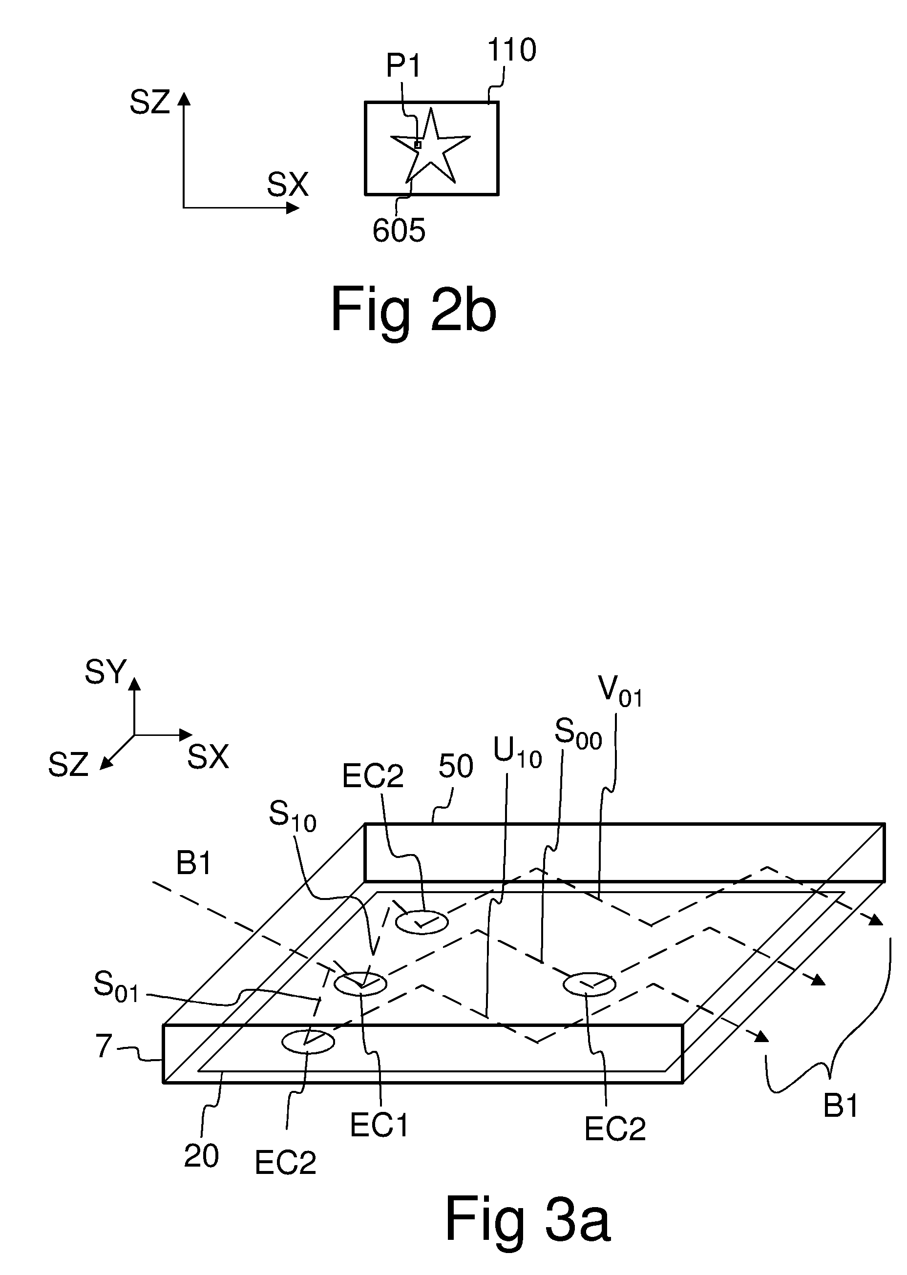
[0042]Referring to FIG. 1, a virtual display device 200 may comprise an optical engine 100 and a diffractive beam expander 50. The optical engine 100 comprises a micro-display 110 and imaging optics 120 (FIG. 2a). The imaging optics 120 converts a real image 605 (FIG. 2b) formed by the micro-display into a virtual image 710 (FIG. 10) which is observable through a viewing aperture 35 of the diffractive beam expander 50.
[0043]The diffractive beam expander 50 comprises an input grating 10, a crossed grating 20, and an output grating 30 implemented on a substantially planar transparent substrate 7. The substrate 7 has a first substantially planar surface, and a second substantially planar surface which is substantially parallel to said first planar surface.
[0044]The substrate 7 is waveguiding, which means that in-coupled light may propagate within said substrate 7 such that said propagating light may be confined to said substrate 7 by total internal reflections (TIR).
[0045]The optical e...
PUM
 Abstract
Description
Claims
Application Information