Managing loop interface instability

a technology of loop interface and instability, applied in the field of managing loop interface instability, can solve problems such as excessive intermittent failure of loops

Active Publication Date: 2012-04-17
EMC IP HLDG CO LLC
View PDF9 Cites 11 Cited by
  • Summary
  • Abstract
  • Description
  • Claims
  • Application Information

AI Technical Summary

Benefits of technology

[0010]A bad device causing intermittent failures can be correctly identified and kept off a Fibre Channel Arbitrated Loop, in order to maintain accessibility to other devices on the same Loop.

Problems solved by technology

It is determined that a loop has excessive intermittent failures.

Method used


Image

  • Managing loop interface instability
  • Managing loop interface instability
  • Managing loop interface instability

Examples


Embodiment Construction

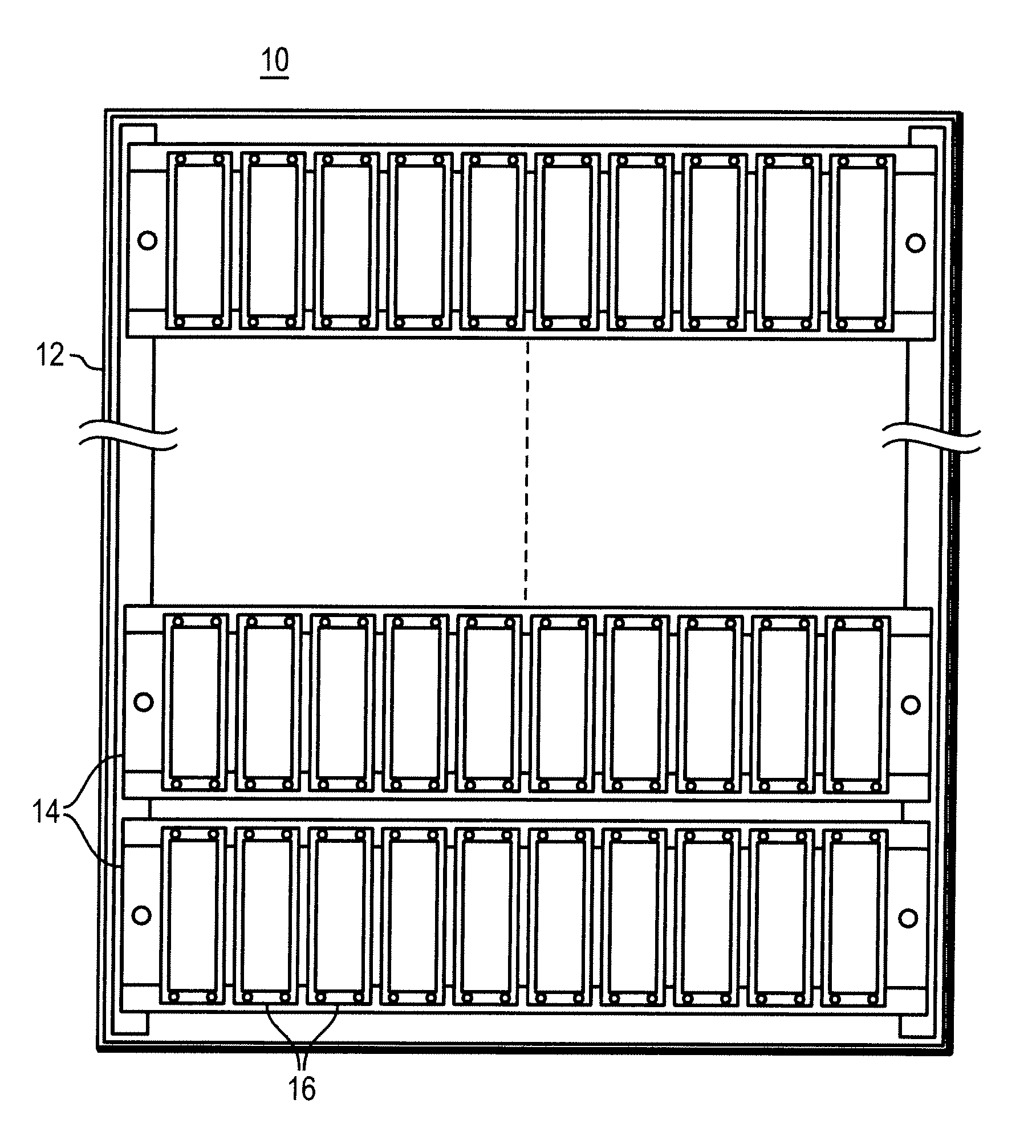
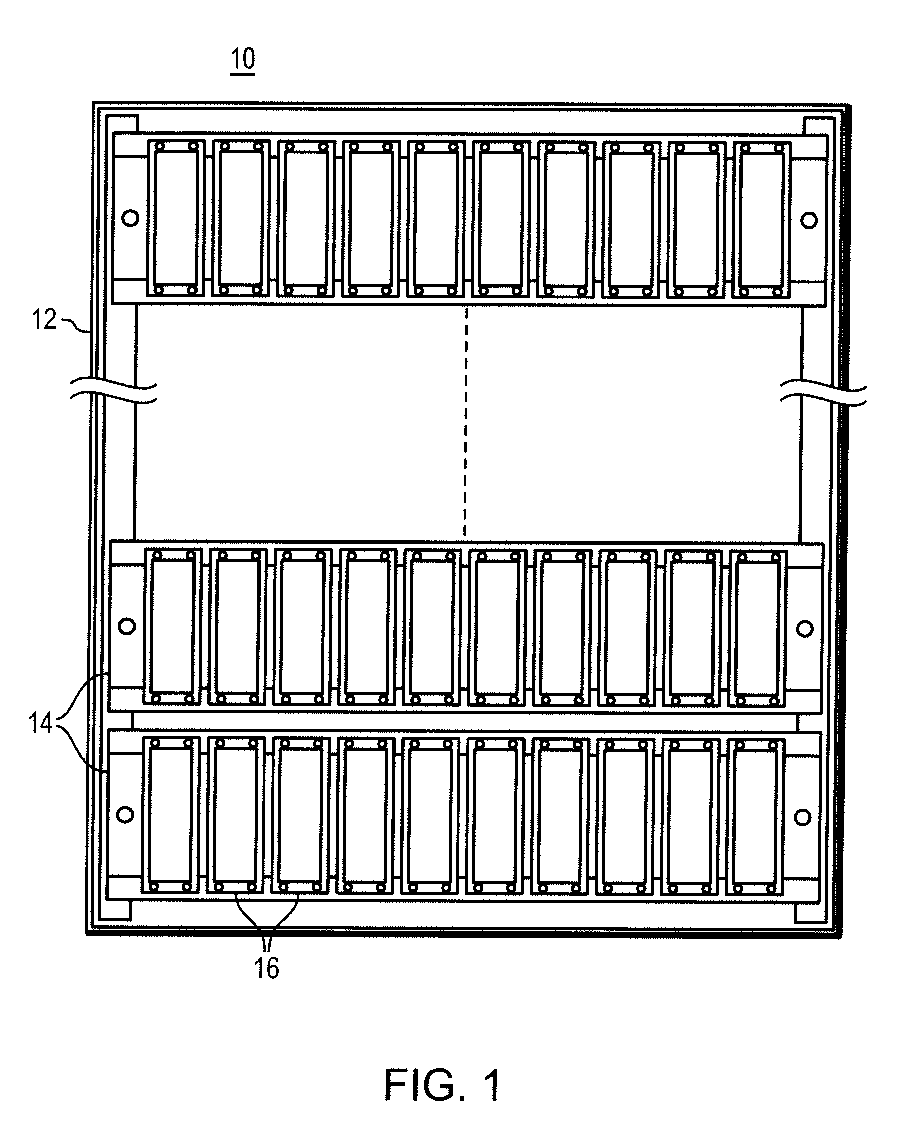
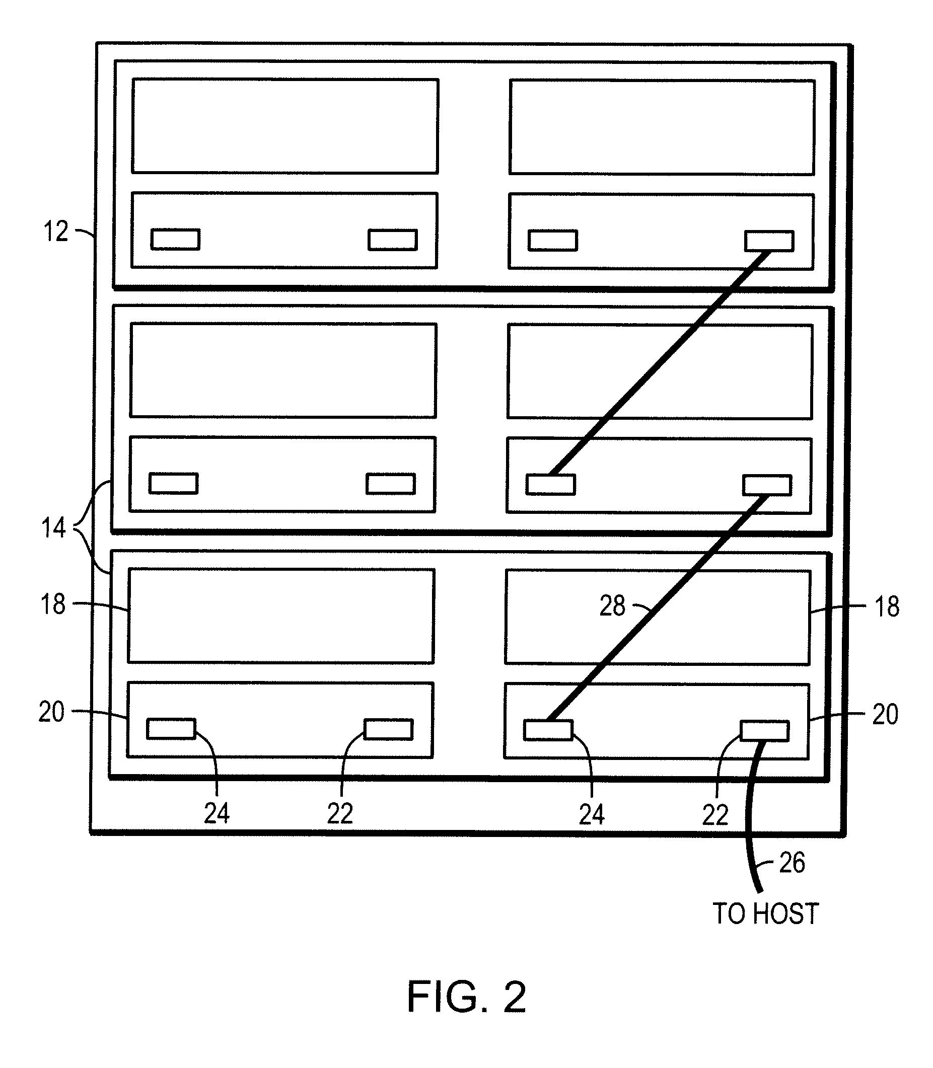
[0016]Described below is a technique for use in managing loop interface instability, particularly for use in identifying a bad component (e.g., a drive, link controller card (LCC), cable or enclosure of an example data storage system described below) causing loop instability.

[0017]Conventionally, in a data storage system, if a component is bad and is causing loop disturbance in such a way that the loop is “bouncing” causing software to re-initialize the loop repeatedly, it can cause input / output data transactions (I / Os) to be queued up and can cause multiple drives to be removed, input / output performance to be degraded, and can ultimately lead to a data unavailable / data loss (DU / DL) situation.

[0018]In particular, conventionally in the data storage system, when bad components cause software to re-discover the loop repeatedly, software holds off I / Os, issues commands so that drives can log back in, and then resumes the I / Os. If this conventional condition keeps repeating within a shor...


PUM


Abstract

A method is used in managing loop interface instability. It is determined that a loop has excessive intermittent failures. It is determined, based on whether the intermittent failures are detectable on another loop, whether the cause of the excessive intermittent failures is within a specific category of components. A search procedure is executed that is directed to the specific category of components, to isolate the cause of the excessive intermittent failures.

Description

FIELD OF THE INVENTION[0001]The present invention relates generally to managing loop interface instability.BACKGROUND OF THE INVENTION[0002]Computers, computer networks, and other computer-based systems are becoming increasingly important as part of the infrastructure of everyday life. Networks are used for sharing peripherals and files. In such systems, complex components are the most common sources of failure or instability. The proliferation of multiple interacting components leads to problems that are difficult or impossible to predict or prevent. The problems are compounded by the use of networks, which introduce the added complexity of multiple machines interacting in obscure and unforeseen ways.[0003]Most complex electronic devices, including computer systems and networked hardware, are designed with built-in diagnostics. These diagnostics are specifically designed for the system and usually detect a fairly wide range of problems. Sometimes they can also implement fixes or wo...

Claims


Application Information

Patent Timeline
Patent Type & Authority Patents(United States)
IPC IPC(8): G06F11/00
CPCG06F11/076G06F11/1092
Inventor MANNING, MICHAELTAMILARASAN, ASHOKCHIU, NAIZHONG
Owner EMC IP HLDG CO LLC
Why Eureka
Try Eureka