
Apparatus for displaying formation of network

a network and display device technology, applied in the field of network formation display devices, can solve the problems of user difficulty in intuitively and quickly understanding the connection relationship, user difficulty in quickly recognizing the display contents, user experience cumbersome change the connection relationship between the terminals, etc., to achieve fast recognition, fast change the connection relationship, and fast recognition

Inactive Publication Date: 2012-04-17
YAMAHA CORP
View PDF64 Cites 4 Cited by
  • Summary
  • Abstract
  • Description
  • Claims
  • Application Information

AI Technical Summary

Benefits of technology

The present invention provides a network formation display apparatus and a signal path establishment apparatus that can intuitively and quickly understand the connection relationship between nodes. The apparatus allows for fast change of the connection relationship between nodes and provides a display screen that can easily display the formation of a network. The apparatus includes an acquiring section that acquires the arrangement of communication paths between nodes, an selecting section that selects the musical performance information or audio signal to be displayed, and a determining section that determines if there are available input terminals for the selected output terminals. The apparatus can also draw lines connecting the selected output and input terminals to logically establish communication paths. The invention provides a network formation display apparatus and a signal path establishment apparatus that can be used in a network of a plurality of nodes for transferring musical performance information and audio signals through communication paths.

Problems solved by technology

Accordingly, users feel it difficult to intuitively and fast understand the connection relationship.
Users also feel it cumbersome to change the connection relationship between the terminals.
Thus, when displaying the other list, the user cannot promptly recognize the display contents.

Method used


Image

  • Apparatus for displaying formation of network
  • Apparatus for displaying formation of network
  • Apparatus for displaying formation of network

Examples


Embodiment Construction

1. Hardware Configuration of an Embodiment

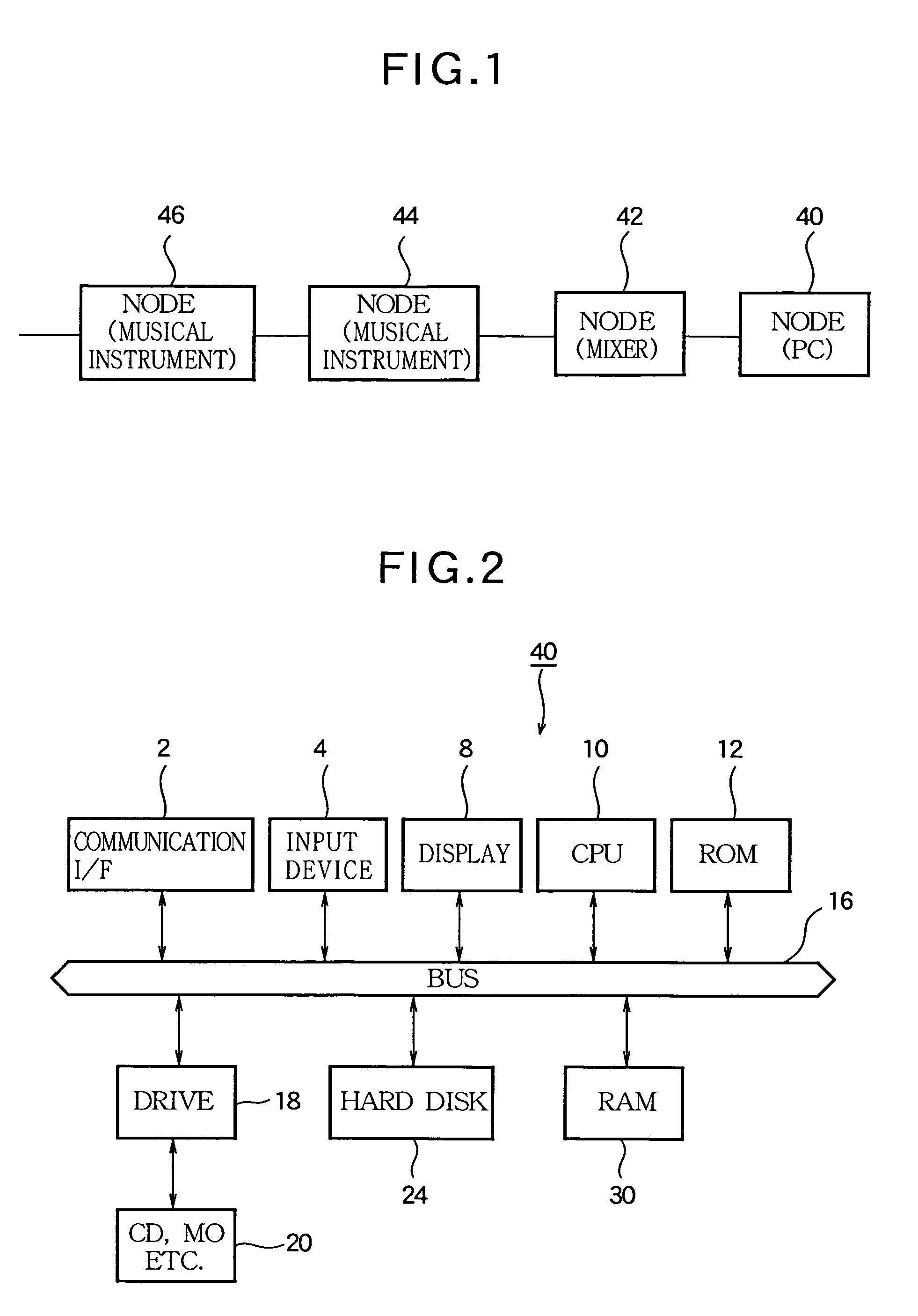
[0034]With reference to FIG. 1, the following describes the configuration of a musical sound signal editing system as an embodiment of the present invention.

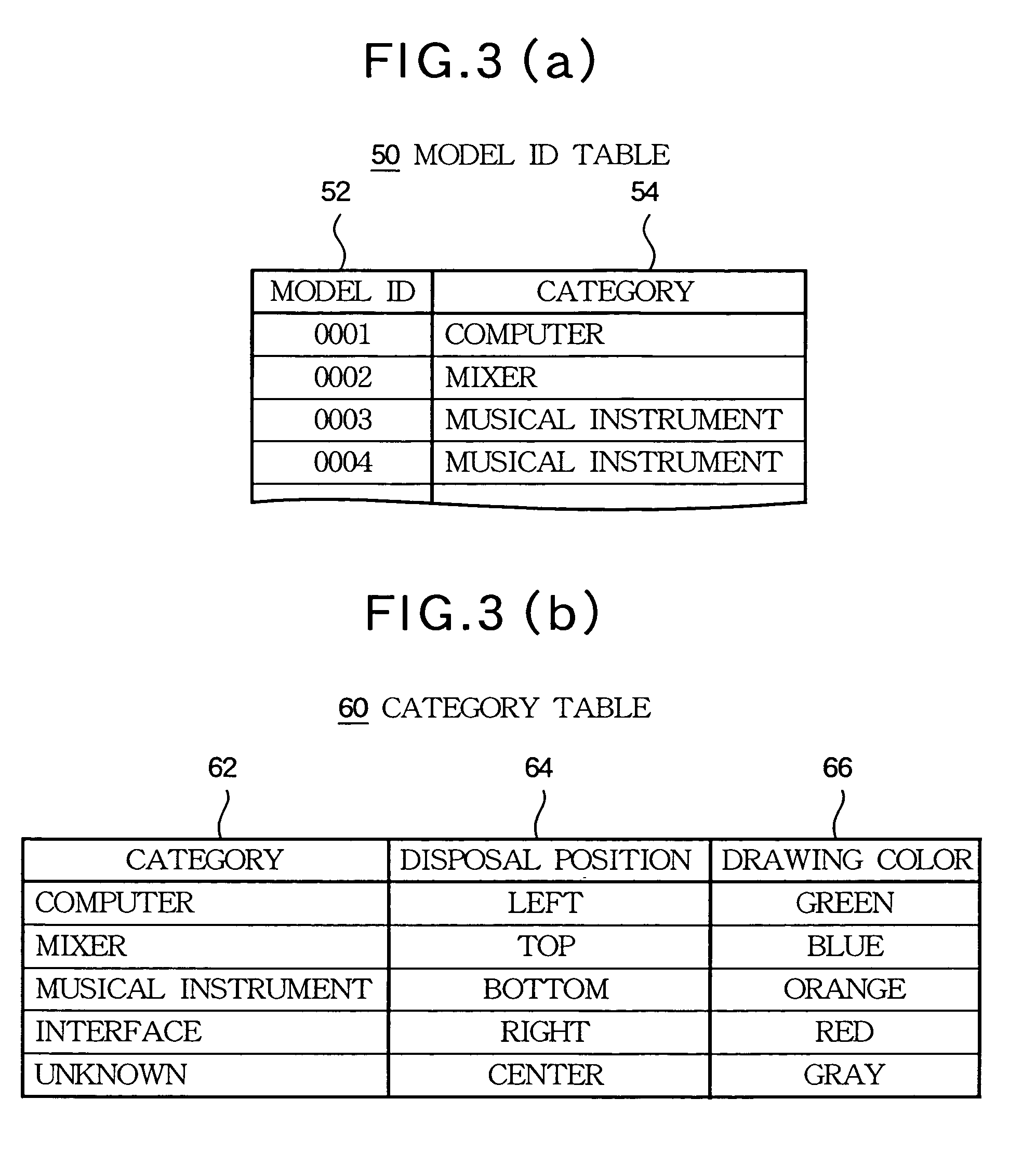
[0035]In FIG. 1, the reference numeral 40 denotes a personal computer; 42 denotes a mixer; and 44 and 46 denote musical instruments constituting nodes on a music LAN. Each node is provided with at least two IEEE1394 ports which are connected in a daisy chain configuration. In addition to the nodes 40 through 46 in FIG. 1, it is assumed that a plurality of nodes are likewise connected to the music LAN. All the nodes are classified into any of “categories” such as “computer”, “mixer”, “musical instrument”, “interface”, and “unknown” according to their types.

[0036]The configuration of the personal computer 40 is described with reference to FIG. 2. The reference numeral 2 denotes a communication interface and is provided with the above-mentioned two IEEE1394 ports and MIDI terminals. The ref...


PUM


Abstract

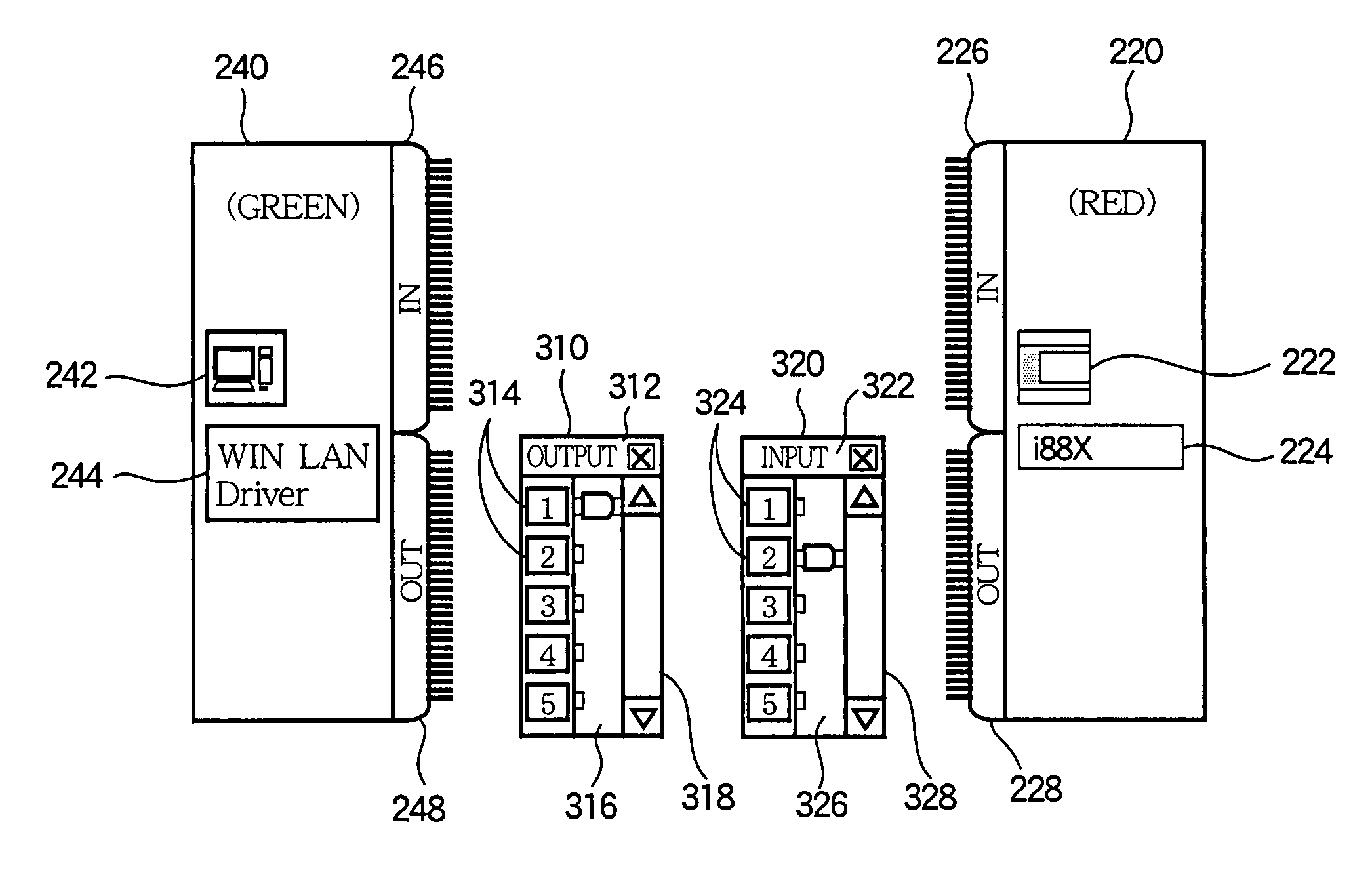
A display apparatus is designed for displaying formation of a network on a screen. The network is composed of a plurality of nodes and is capable of transferring either of musical performance information and an audio signal through communication paths connecting the plurality of the nodes. In the display apparatus, an acquiring section acquires a type of each node and an arrangement of the communication paths arranged among the nodes for transmitting and receiving the musical performance information and the audio signal. An allocating section allocates a display area to each node within the screen according to the acquired type of each node. A drawing section draws a plurality of index images indicating the respective nodes on the screen at the display areas allocated to the respective nodes, and draws lines connecting the displayed index images of the nodes on the screen according to the acquired arrangement of the communication paths.

Description

BACKGROUND OF THE INVENTION[0001]1. Technical Field[0002]The present invention relates to a network formation display apparatus and a signal path establishment apparatus suitably used for transmission and reception of Musical Instrument Digital Interface (MIDI) signals or audio signals between a plurality of networked nodes.[0003]2. Related Art[0004]Conventionally, the applicants propose the music LAN (mLAN, registered trademark) that constructs a local area network (LAN) comprising nodes such as a personal computer, an electronic musical instrument, a mixer, an effector, and a recorder, and freely sends and receives MIDI signals and audio signals between the nodes. The music LAN is disclosed in Japanese Non-examined Patent Publication No. 2001-203732. The music LAN complies with the IEEE1394 standard. Normally, each node is provided with two IEEE1394 ports. The IEEE1394 ports of each node are connected in a daisy chain configuration to build up a hardware connection of the music LA...

Claims


Application Information

Patent Timeline
Patent Type & Authority Patents(United States)
IPC IPC(8): G06F15/177H04L12/24H04Q11/00
CPCH04L41/12H04L41/22
Inventor TAKEDA, FUMITERUMUTO, TAKAAKI
Owner YAMAHA CORP
Learn More