Wind turbine blade and a pitch controlled wind turbine

a wind turbine blade and pitch control technology, which is applied in the direction of wind turbines, machines/engines, wind energy generation, etc., can solve the problems of large risk of being ripped off the blade, harsh environment on the outside surface of the wind turbine blade, etc., and achieve the effect of reducing the sound emission

Active Publication Date: 2012-04-24
VESTAS WIND SYST AS
View PDF18 Cites 64 Cited by
  • Summary
  • Abstract
  • Description
  • Claims
  • Application Information

AI Technical Summary

Benefits of technology

[0012]Providing the joint between the turbulence generating strips and the surface of the blade with a sealer is advantageous, in that it hereby is possible to prevent the wind from gripping the joint and tearing the strip of and at the same time it is possible to prevent that dirt, water or other enters the joint and degrades the strips hold on the blade. Hereby it is ensured that the strips stay in place and maintains they function for a long time, preferably the entire lifespan of the wind turbine blade
[0051]Variable rotation speeds produces variable noise at variable levels which can be particularly irritating to the human ear. It is therefore advantageous to reduce the sound emission by use of turbulence generating strips on the blades of a variable speed pitch controlled wind turbine.

Problems solved by technology

The outside surface of a wind turbine blade presents a very harsh environment and particularly turbulence generating strips, which are intended to stir up the airflow to some degree, are at great risk of being ripped of the blade, either simply because of the high wind speeds or because dirt, rain or other slowly works its way into the joint between the strips and the blade surface.

Method used


Image

  • Wind turbine blade and a pitch controlled wind turbine
  • Wind turbine blade and a pitch controlled wind turbine
  • Wind turbine blade and a pitch controlled wind turbine

Examples


Embodiment Construction

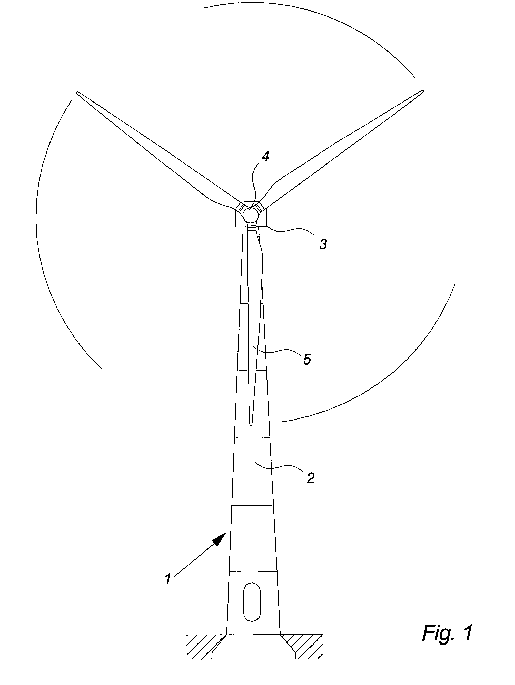
[0060]FIG. 1 illustrates a modern wind turbine 1, comprising a tower 2 and a wind turbine nacelle 3 positioned on top of the tower 2. The wind turbine rotor 4, comprising three wind turbine blades 5, is connected to the nacelle 3 through the low speed shaft which extends out of the nacelle 3 front.

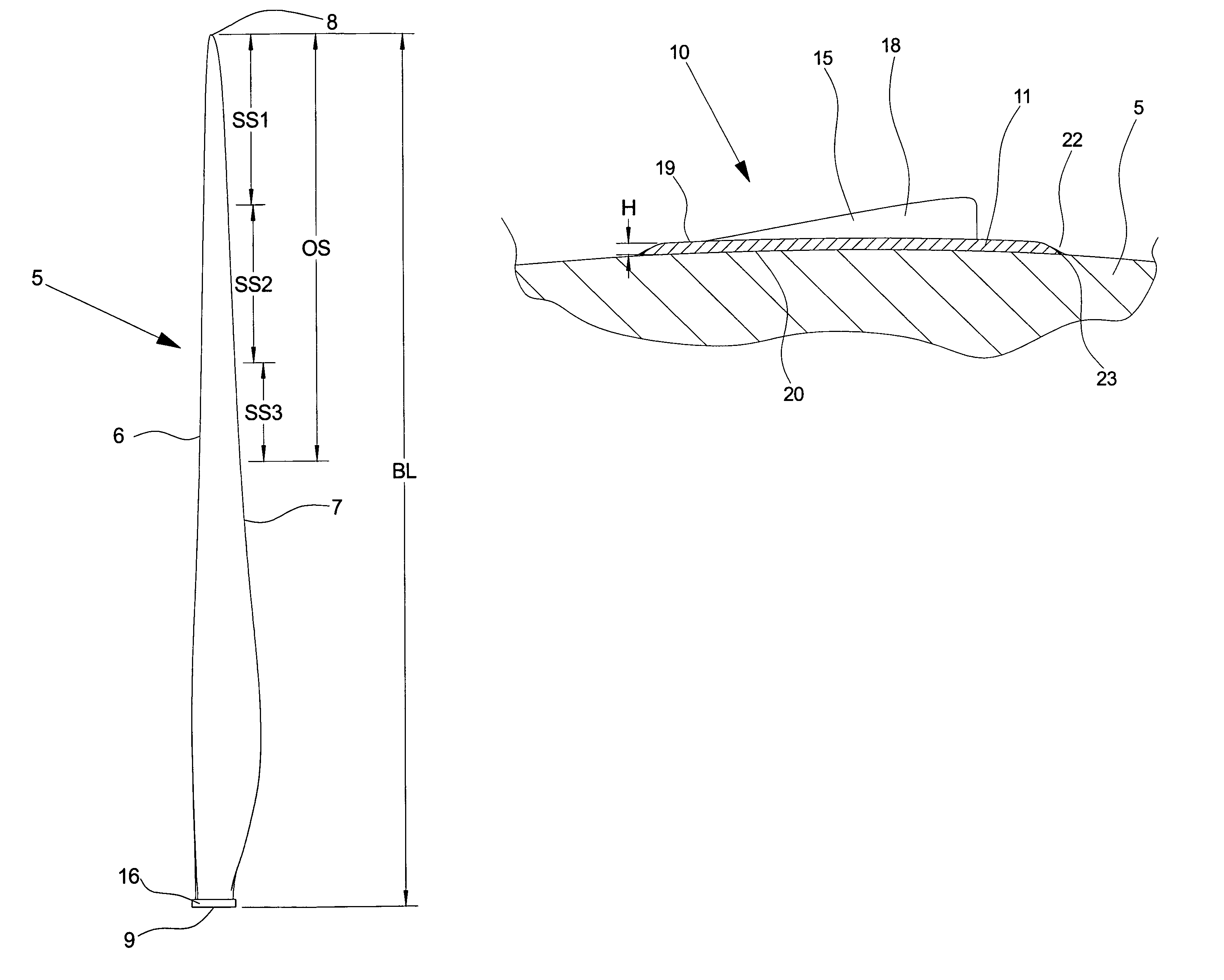
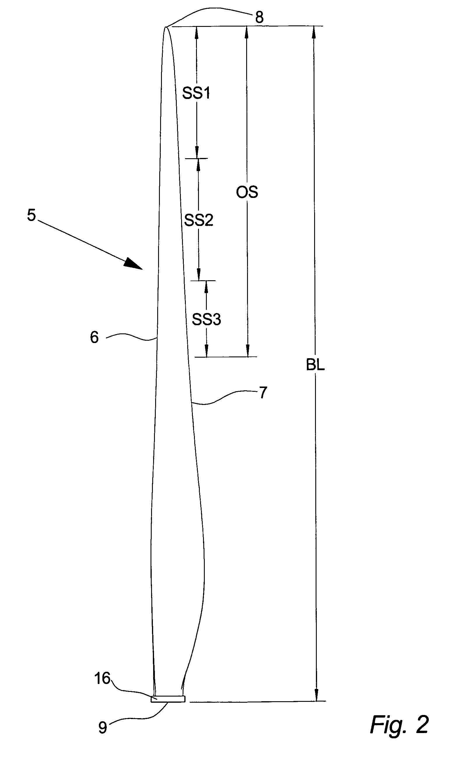
[0061]FIG. 2 illustrates a wind turbine blade 5 for a pitch controlled wind turbine 1, as seen from the front / pressure side 14. The wind turbine blade 5 comprises a leading edge 6, a trailing edge 7, a tip 8 and a root 9. A wind turbine blade 5 known in the art is typically made of a glass fibre and resin composite reinforced by carbon fibre, carbon fibre reinforced wood or a combination hereof.

[0062]The length of the blade 5 is indicated by BL.

[0063]At the root 9 the blade 5 is provided with a pitch controlling unit 16 which could comprise bearings, gear wheel, means for pitching the blade 5 and / or means for attaching the means for pitching the blade 5.

[0064]During normal operation of a w...


PUM


Abstract

The invention relates to a wind turbine blade comprising one or more turbulence generating strips, where the strips are placed on a surface of the blade. The blade is characterized in that at least one joint area of the turbulence generating strips and the surface of the blade are completely or partially covered by sealing means. The invention further relates to a pitch controlled wind turbine comprising at least two pitch controlled wind turbine blades and pitch controlling means for pitching the blades. The pitch controlled wind turbine is characterized in that the blades comprises one or more turbulence generating strips, wherein at least one joint area of the turbulence generating strips and a surface of the blades are completely or partially covered by sealing means.

Description

CROSS-REFERENCE TO RELATED APPLICATIONS[0001]The present application is a continuation of pending International patent application PCT / DK2006 / 000326 filed on Jun. 9, 2006 which designates the United States and the content of which is incorporated herein by reference.FIELD OF THE INVENTION[0002]The invention relates to a wind turbine blade comprising one or more turbulence generating strips, with strips being placed on a surface of the blade and attached to the surface by means of adhesive. The invention also relates to a pitch controlled wind turbine wherein one or more turbulence generating strips are placed on an outer section of the wind turbine blades in direction of the blade tip, the outer section ranging from 60% to 100% of the length of the blade e.g. the outermost third of the wind turbine blade.BACKGROUND OF THE INVENTION[0003]A wind turbine known in the art comprises a wind turbine tower and a wind turbine nacelle positioned on top of the tower. A wind turbine rotor with ...

Claims


Application Information

Patent Timeline
Patent Type & Authority Patents(United States)
IPC IPC(8): F03D1/06F03D11/00
CPCF03D1/0633F03D1/0675F03D7/0224Y02E10/723F05B2240/21F05B2240/32F05B2250/61F05B2260/96Y02E10/721Y10S415/914Y02E10/72F05B2240/3062
Inventor HAAG, MICHAEL DRACHMANN
Owner VESTAS WIND SYST AS
Why Eureka
Try Eureka