
Low vibration pump

a low-vibration, pump technology, applied in the direction of pump components, positive-displacement liquid engines, liquid fuel engine components, etc., can solve the problems of large size, complex structure of pulsation absorbing units, and inability to avoid discharge pressure pulsation, so as to reduce the rotational speed and downsize the pump

Active Publication Date: 2012-04-24
NITTO KOHKI CO LTD
View PDF23 Cites 8 Cited by
  • Summary
  • Abstract
  • Description
  • Claims
  • Application Information

AI Technical Summary

Benefits of technology

[0009]In this low vibration pump, the second diaphragm is pressurized by means of the spring member. Therefore, even if pulsation applied to the pulsation absorbing chamber is of high frequency, the second diaphragm can properly absorb the pulsation. Further, the volume occupied by the spring member can be small, whereby it is possible to downsize the pump as a whole.
[0014]In the present invention, even if pulsation applied to the pulsation absorbing chamber is of high frequency, it is possible to properly absorb the pulsation. Therefore, the pump can be operated at a high frequency by means of the electric rotary motor without reducing the rotational speed. Further, it is possible to downsize the pump including the pulsation absorbing unit.

Problems solved by technology

In use of such a reciprocating liquid pump, the occurrence of discharge pressure pulsation cannot be avoided.
However, in such a conventional reciprocating liquid pump with a pulsation absorbing unit, the pulsation absorbing unit is complicated in structure and large in size, which is not suitable for a small-sized liquid pump in which reciprocation period is short.

Method used


Image

  • Low vibration pump
  • Low vibration pump
  • Low vibration pump

Examples


Embodiment Construction

[0022]An embodiment of a reciprocating fluid pump with a pulsation absorbing unit to which the present invention is applied will now be described with reference to the accompanying drawings.

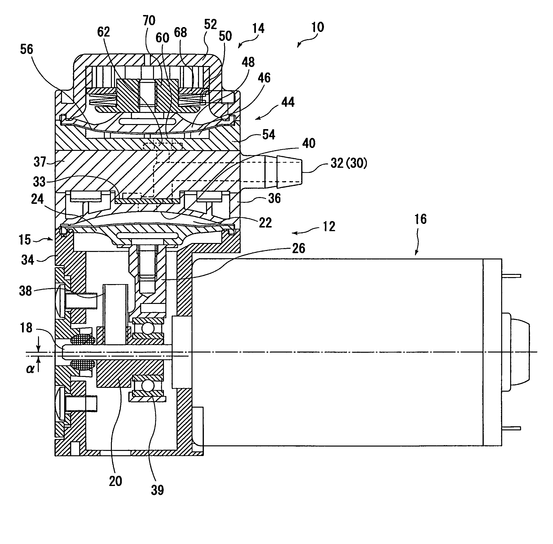
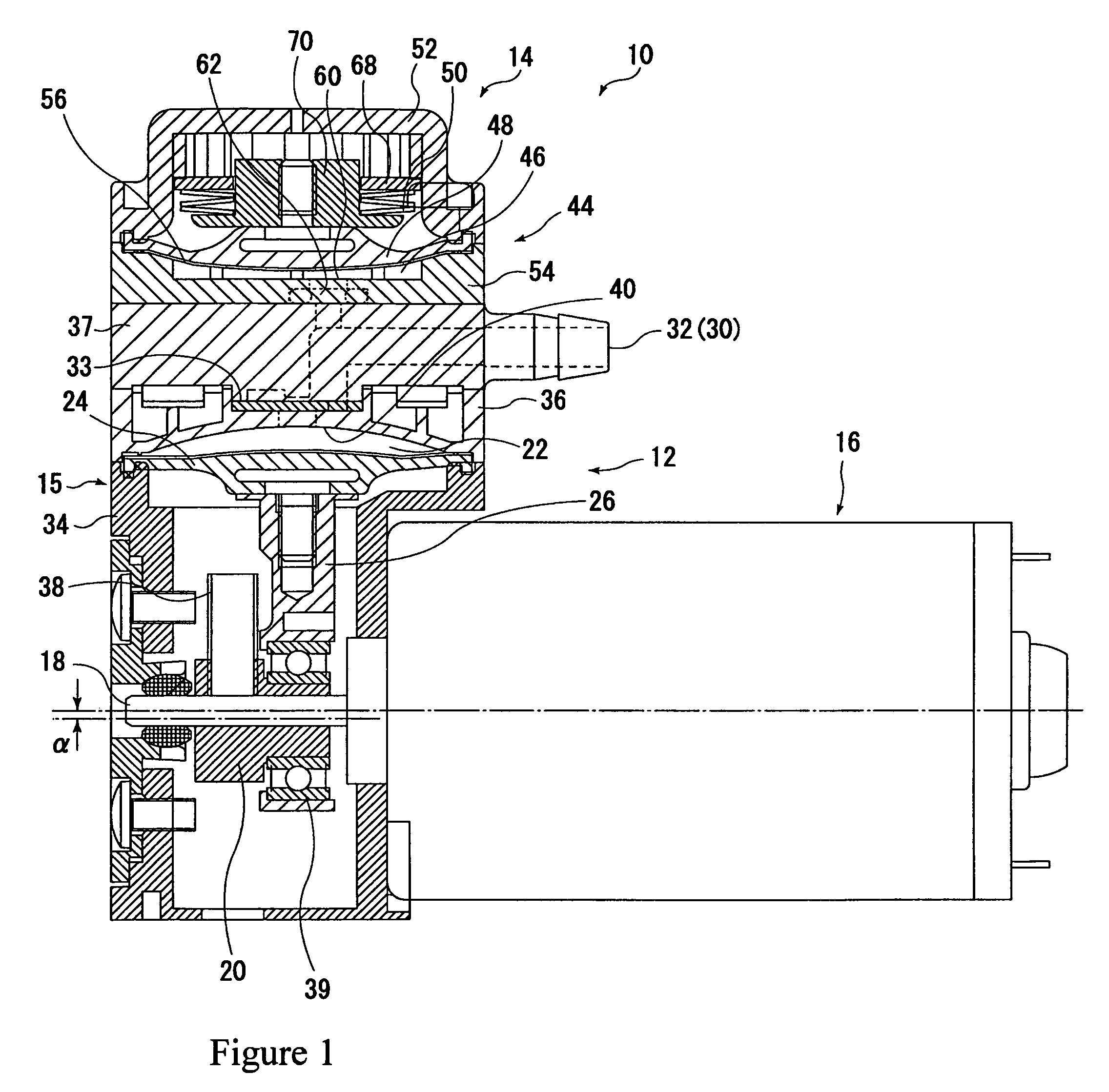
[0023]FIG. 1 shows a sectional side view of a low vibration pump 10 according to the present invention.

[0024]As shown in the figure, the pump includes a liquid pump unit 12 and a pulsation absorbing unit 14.

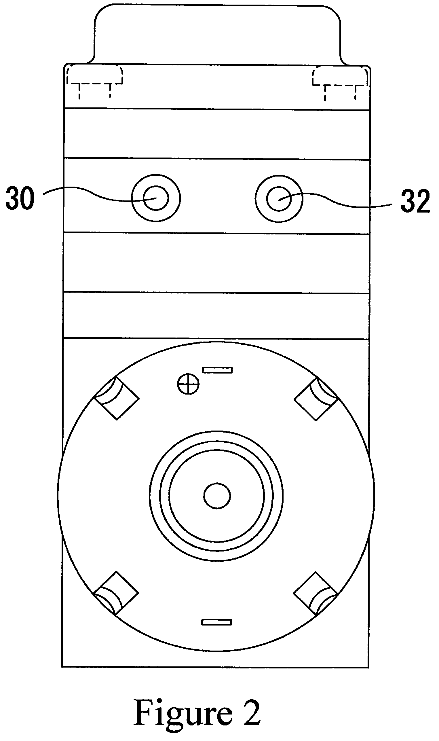
[0025]The liquid pump unit 12 includes a pump housing 15, a DC motor 16, an eccentric cam 20 drivingly rotated by means of a rotating output shaft 18 of the DC motor 16, a first diaphragm 24 attached to the pump housing 15 and defining a pump chamber 22 in the pump housing, a connecting rod 26 connected between the eccentric cam 20 and the first diaphragm 24 and reciprocally deforming the first diaphragm 24 in a direction perpendicular to the axial direction of the rotating output shaft 18 according to the rotation of the eccentric cam 20, a liquid inlet passage 30 (FIG. 2) for receiving liqui...


PUM


Abstract

A liquid pump is provided in which pulsations can be properly absorbed even if the pump is driven at a high frequency. A pulsation absorbing unit for absorbing pulsation includes a pulsation absorbing housing disposed on a pump housing member, a second diaphragm attached to the pulsation absorbing housing member and defining a pulsation absorbing chamber communicating with a liquid outlet passage of a liquid pump unit, and a disc spring for biasing the second diaphragm toward the pulsation absorbing chamber.

Description

BACKGROUND OF THE INVENTION[0001]I. Technical Field[0002]The present invention relates to a low vibration pump in which a pulsation absorbing unit is integrally provided to a pump for sucking and discharging liquid by reciprocation.[0003]II. Description of the Related Art[0004]In use of such a reciprocating liquid pump, the occurrence of discharge pressure pulsation cannot be avoided. Therefore, according to the application and the intended use of an object to which pressure is supplied, pumps having a structure in which the pulsation can be reduced have been developed. (for example, Japanese Patent Application Publication No. 2001-355568)[0005]However, in such a conventional reciprocating liquid pump with a pulsation absorbing unit, the pulsation absorbing unit is complicated in structure and large in size, which is not suitable for a small-sized liquid pump in which reciprocation period is short.SUMMARY OF THE INVENTION[0006]In view of the foregoing, it is an object of the present...

Claims


Application Information

Patent Timeline
IPC IPC(8): F04B11/00
CPCF04B11/0033F04B43/02
Inventor MIZUNO, KENJIOKI, YASUMASA
Owner NITTO KOHKI CO LTD
Learn More