Bending system

a technology of bending head and bending head, which is applied in the field of bending head, can solve the problems of reducing the space requirements of the system considerably, and achieve the effect of ensuring the same tolerances and precision, and not reducing the rotational speed of the bending head

Inactive Publication Date: 2005-07-07
MARTINREA INT INC
View PDF8 Cites 5 Cited by
  • Summary
  • Abstract
  • Description
  • Claims
  • Application Information

AI Technical Summary

Benefits of technology

[0010] The present invention overcomes these disadvantages in a bending system which is capable of bending long tubes, wires and other elements into complex three dimensional configurations, with the same tolerances and precision as short tubes and without reducing the rotational speed of the bending head.
[0011] The invention accomplishes this by providing a series of bending stations, each equipped with a bending head. The workpieces are conveyed from bending station to bending station by grippers that preferably grasp the workpiece at an intermediate portion, rather than at one end. This reduces the length of workpiece from the gripping point to the free ends, commensurately reducing twisting and wobbling of the workpiece during bending and significantly diminishing the likelihood of slippage of the workpiece in the gripper during rotation.
[0012] The bending stations may also be spaced from one another a distance which is shorter than the length of a workpiece, because each bending head grasps the tube at a different intermediate position so the bending stations do not interfere with one another. Moreover, in the preferred embodiment each bending station is capable of rotating, to position the bending dye such that the free end of the workpiece being bent can be oriented in the bending plane without interference by an adjacent bending station. These features reduce the space requirements of the system considerably.

Problems solved by technology

These features reduce the space requirements of the system considerably.

Method used


Image

  • Bending system
  • Bending system
  • Bending system

Examples


Embodiment Construction

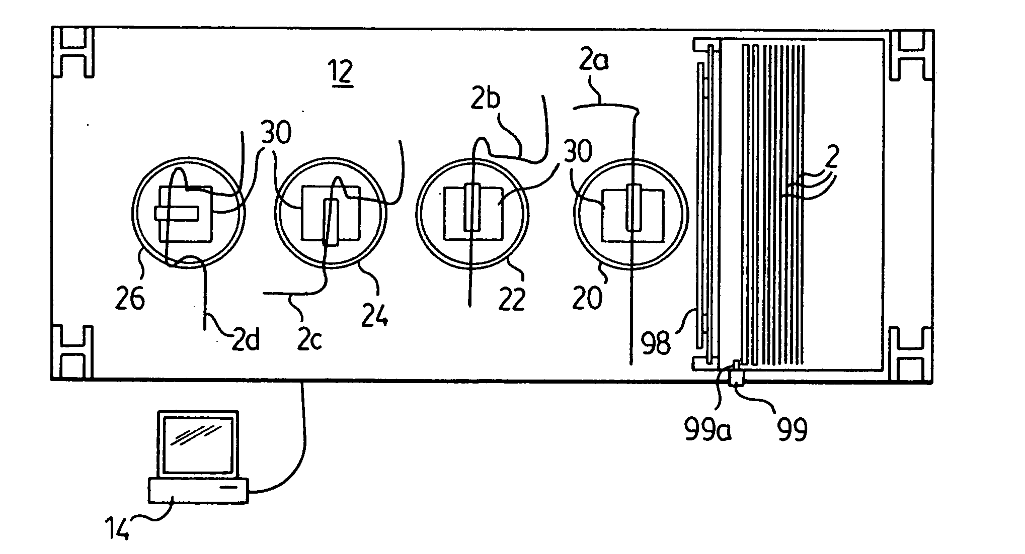
[0027] The bending system of the invention will be described herein in the context of bending tubes 2, for example tubes used for fluid conduits in an automobile such as brake lines. However, it will be appreciated that the principles of the invention apply to bending any bendable elongated member, and the invention is not intended to be limited to any particular type of workpiece.

[0028] The bending system 10 of the invention comprises a series of bending stations 20, 22, 24, 26, shown in FIGS. 5 and 6. There are four bending stations in the embodiment illustrated, however it will be appreciated that more or fewer bending stations may be employed, depending upon the complexity of the bending to be accomplished and the desired output of the system.

[0029] Each bending station comprises a pedestal 28, which is rotatably mounted into a floor 12 of the system 10, and a bending head 30 having a bending arm 32 that follows an arcuate path about a dye 34 along a bending plane B, as is con...


PUM

PropertyMeasurementUnit
lengthaaaaaaaaaa
sizesaaaaaaaaaa
bendingaaaaaaaaaa

Abstract

A bending system comprising a series of bending stations, each equipped with a bending head. Workpieces are conveyed from one bending station to the next by grippers suspended from a two-axis gantry, that preferably grasp the workpiece at an intermediate portion. Each bending head grasps the tube at a different intermediate position, and in the preferred embodiment each bending station is capable of rotating to position the bending dye such that the free end of the workpiece being bent can be oriented in the bending plane without interference by an adjacent bending station. These features reduce the space requirements of the system considerably. A multi-level dispensing apparatus may be provided to load the bending heads. The bending system is preferably operated by computer, allowing the bending of long workpieces to precise configurations under the control of a single operator.

Description

FIELD OF THE INVENTION [0001] This invention relates to industrial equipment. In particular, this invention relates to a bending system for bending wires, tubes and other elements, for example for use as components in manufacturing. BACKGROUND OF THE INVENTION [0002] Bent components are used in manufacturing many different types of articles and machines. For example, many of the fluid conduits in an automobile are bent to a predetermined shape for installation on an automobile assembly line. In such situations the component must be shaped to exacting tolerances, particularly in the case of for example brake lines which carry brake fluid from the master braking cylinder to the wheel cylinders, in order to ensure that the conduits fit into the space for which they are designed and conduits are stable in motion. [0003] One popular bending method is known as “draw bending”, in which the workpiece is held in position and bent by a bending arm around a dye having a set radius of curvature...

Claims


Application Information

Patent Timeline
Patent Type & Authority Applications(United States)
IPC IPC(8): B21D7/024
CPCB21D7/024
Inventor BURTON, DAVIDREA, NAT
Owner MARTINREA INT INC
Why Eureka
Try Eureka