
Programmable/tunable active RC filter
a programmable/tunable, active technology, applied in the field of analog filter circuits, can solve the problems of reducing control efficiency, increasing the number of circuit devices, and becoming more difficult to design in an integrated circui
- Summary
- Abstract
- Description
- Claims
- Application Information
AI Technical Summary
Benefits of technology
Problems solved by technology
Method used
Image

Examples
Embodiment Construction
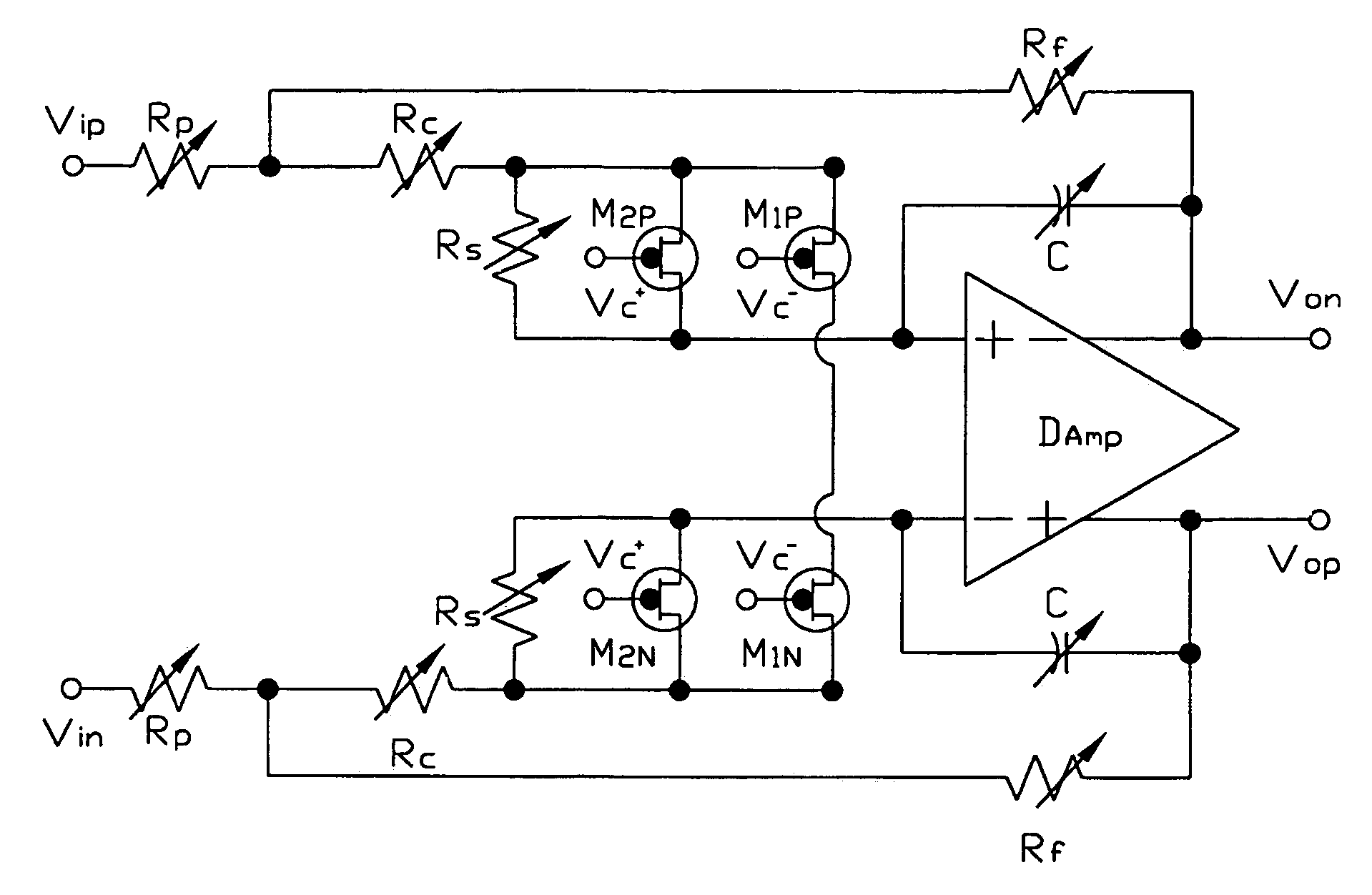
[0018]The following descriptions about the circuit of the present invention not include the complete structure of the active filter. It just quotes the key points of traditional techniques for illustrates the present invention. Moreover, all of the drawings relates to the present invention don't accord the scale, they are just used to represent the characteristics of structure of present invention.
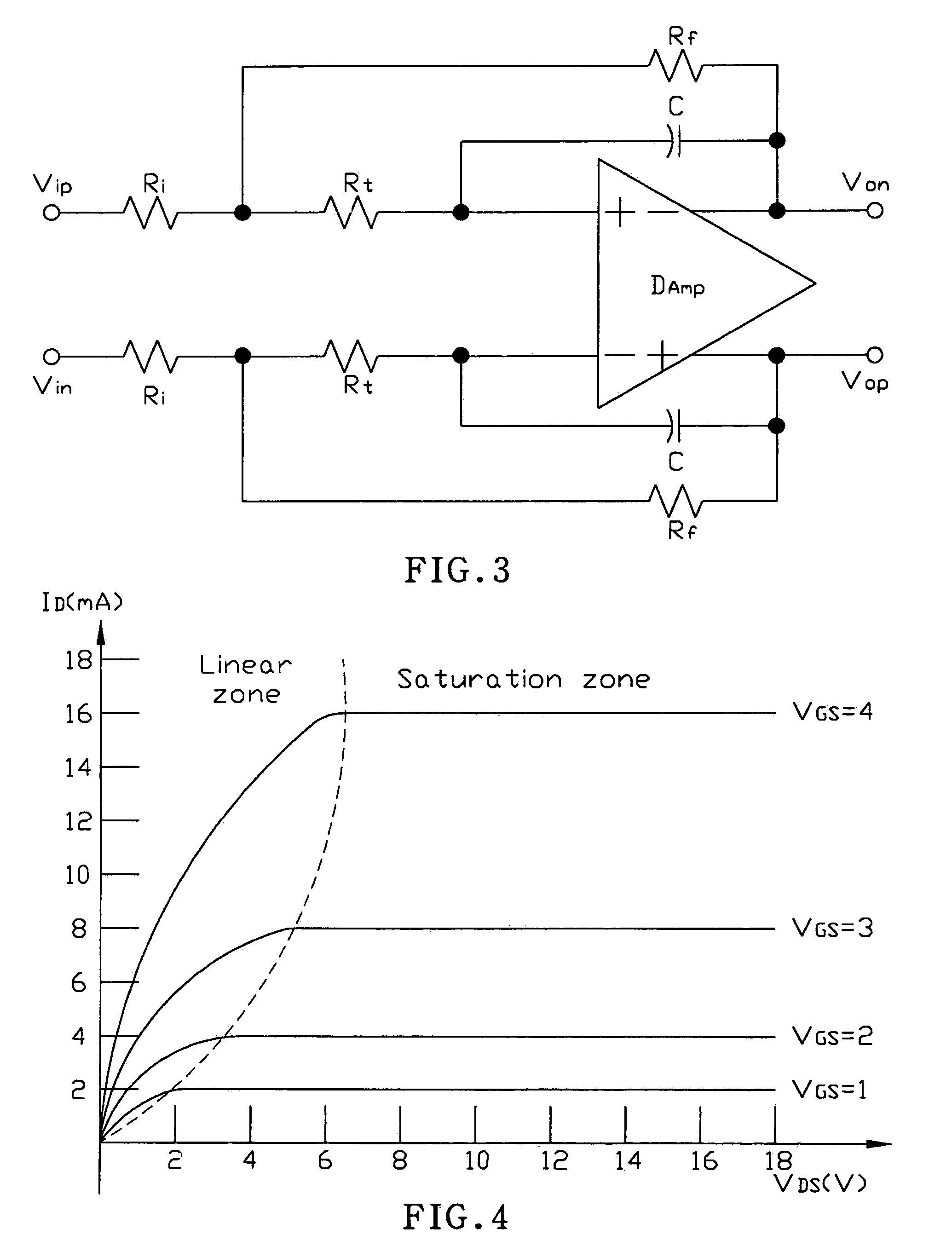
[0019]FIG. 3 depicts an embodiment according to the present invention. The circuit is composed of a differential amplifier DAmp with two input terminals and two output terminals, the resistors Rf, Ri, Rt and the capacitor C. The upper half-portion and the lower half-portion are symmetry since the differential amplifier of the embodiment is composed of two input terminals and two output terminals. By using the small-signals analysis method to obtain the equivalent resistance Re and the cut-off frequency Fcut:
[0020]Re=Rf+(1+RfRi)×RtΩFcut=12π×[Rf+Rt×(1+RfRi)]×CHz
[0021]According to the abo...
PUM
 Abstract
Description
Claims
Application Information