Oblique incident laser particle analyzer

A laser particle size analyzer and oblique incidence technology, applied in the field of particle size analyzer, can solve the problems of small angle range, low sensitivity and resolution, and achieve the effect of expanding the receiving angle, increasing the sensitivity and resolution, and improving the particle size distribution range.

Active Publication Date: 2012-07-18
丹东百特仪器有限公司
View PDF8 Cites 6 Cited by
  • Summary
  • Abstract
  • Description
  • Claims
  • Application Information

AI Technical Summary

Problems solved by technology

[0003] In view of the above-mentioned deficiencies in the prior art, the technical problem to be solved by the present invention is to provide an oblique incident laser particle size an

Method used


Image

  • Oblique incident laser particle analyzer
  • Oblique incident laser particle analyzer
  • Oblique incident laser particle analyzer

Examples


Embodiment 1

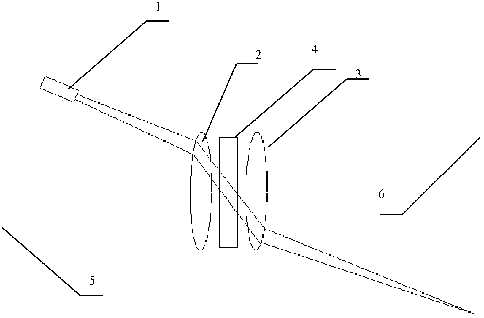
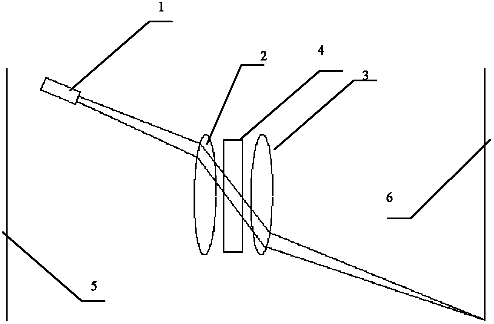
[0022] Such as figure 1 Shown, the structure diagram of oblique incident laser particle size analyzer of the present invention, this particle size analyzer comprises laser 1, lens group, sample cell 4 and viewfinder, lens group is made up of front lens 3 and rear lens 2 of the same optical axis, front lens 3 and the rear lens 2 are respectively placed on the front and rear sides of the sample cell 4; the sample cell 4 is a rectangular sample cell, and the center of the sample cell 4 is placed on the optical axis of the lens group when placed. The laser 1 is placed above the optical axis and placed obliquely on the rear side of the rear lens 2. The height of the laser 1 from the optical axis and the angle of inclination ensure that the laser light emitted by the laser 1 passes through the edge of the rear lens 2 and enters the center of the sample pool obliquely; The "edge part" mentioned here means that the laser beam is not vertically incident, and the position where the lase...

Embodiment 2

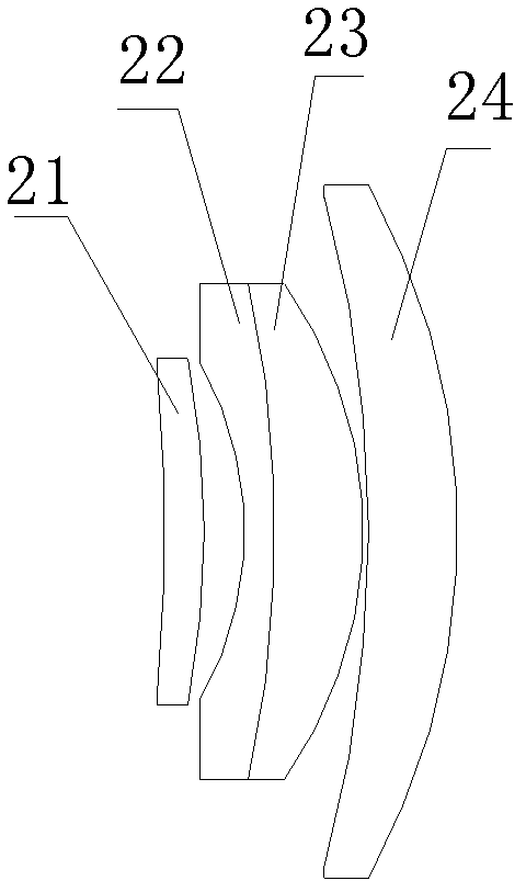
[0029] The difference with Embodiment 1 is that the angle between the laser along the optical path direction and the optical axis of the lens group is 47°, the ratio of the curvature radius of the front surface of the lens I to the radius of curvature of the rear surface is 2; the curvature of the front surface of the lens II The ratio of the radius of curvature to the radius of curvature of the back surface is 4.5; the ratio of the radius of curvature of the front surface of lens III to the radius of curvature of the back surface is 0.4; the ratio of the radius of curvature of the front surface of lens IV to the radius of curvature of the back surface is 0.6.

[0030] The diameter ratios of lens II, lens III and lens IV to lens I are: 1:1, 1.6:1 and 4:1, respectively.

[0031] When the present invention is in use, the laser beam passes through the rear lens, and the rear lens acts as a collimating lens to convert the divergent beam into a parallel beam and then enters the samp...


PUM


Abstract

The invention discloses an oblique incident laser particle analyzer for realizing the measurement of a full-range (0-180 degrees) scattering angle. The oblique incident laser particle analyzer comprises a laser, a lens group, a sample cell and viewfinders. The oblique incident laser particle analyzer is characterized in that the lens group consists of a front lens and a rear lens which share the same optical axis; the front lens and the rear lens are respectively arranged at the front side and the rear side of the sample cell, so that the center of the sample cell is positioned on the optical axis; the laser is obliquely arranged at the rear side of the rear lens; emitted laser beams pass through the edge part of the rear lens to form parallel light which obliquely enters the center of the sample cell; and the viewfinders comprise a front viewfinder positioned at the front part of the front lens and a rear viewfinder positioned at the rear lens and can be used for receiving a scattering light signal from particles in the sample cell. According to the oblique incident laser particle analyzer, the problems of low sensitivity and resolution caused by narrow range of the scattering angle received by the lenses are solved; and the oblique incident laser particle analyzer has the characteristics of high sensitivity and resolution, high test accuracy, wide range of measuring the particle size distribution, and the like.

Description

technical field [0001] The invention relates to a particle size analyzer, in particular to an oblique-incidence laser particle size analyzer capable of measuring scattering angles in a full range (0-180 degrees). Background technique [0002] In the prior art, laser particle size analyzers generally use vertical incident lasers, which use the radius range of the lens to gather scattered light. The angle range of scattered light that it can receive is small, and the sample cell is usually a rectangular window, which will be affected by the parallel glass surface. There is a limitation of the total reflection angle, usually the scattered light in the sample cell greater than 48 degrees cannot be emitted from the sample cell. In this way, the angle of receiving scattered light of the optical path of the traditional laser particle size analyzer is greatly limited. Theoretically speaking, the larger the angle at which the laser particle size analyzer can receive scattered light,...

Claims


Application Information

Patent Timeline
IPC IPC(8): G01N15/02
Inventor 范继来董青云
Owner 丹东百特仪器有限公司
Why Eureka
Try Eureka