Preparation process of infrared receiving head with large receiving angle for air conditioner

A technology of infrared receiving head and receiving angle, applied in the field of infrared receiving head, can solve the problems such as the remote control function of the air conditioner remote control cannot be used normally, the receiving angle of the infrared receiving head is small, and the infrared receiving head is invalid, etc. Good effect, the effect of increasing the receiving area

Pending Publication Date: 2022-05-24
江苏国中芯半导体科技有限公司
View PDF0 Cites 0 Cited by
  • Summary
  • Abstract
  • Description
  • Claims
  • Application Information

AI Technical Summary

Problems solved by technology

The existing infrared receiving head bracket, after packaging, the connection between the bracket and the packaging layer is not reliable, and the bracket may become loose after a long time of use, resulting in disconnection of the lead wires, invalidating the infrared receiving head, and reducing the service life
And this kind of infrared receiving head also has the shortcomings of small receiving angle and poor anti-interference ability, so when the distance is a little far or the angle is a little bit off, the remote control function of the air conditioner remote control will not work normally, which brings certain problems to the use. Trouble
[0003] Therefore, under the existing technical solutions, the problems of small receiving angle and short service life of the infrared receiving head for air conditioners need to be solved urgently.

Method used


Image

  • Preparation process of infrared receiving head with large receiving angle for air conditioner
  • Preparation process of infrared receiving head with large receiving angle for air conditioner
  • Preparation process of infrared receiving head with large receiving angle for air conditioner

Examples


Embodiment Construction

[0031] The technical solutions in the embodiments of the present invention will be clearly and completely described below with reference to the accompanying drawings in the embodiments of the present invention. Obviously, the described embodiments are only a part of the embodiments of the present invention, rather than all the embodiments. Based on the embodiments of the present invention, all other embodiments obtained by those of ordinary skill in the art without creative efforts shall fall within the protection scope of the present invention.

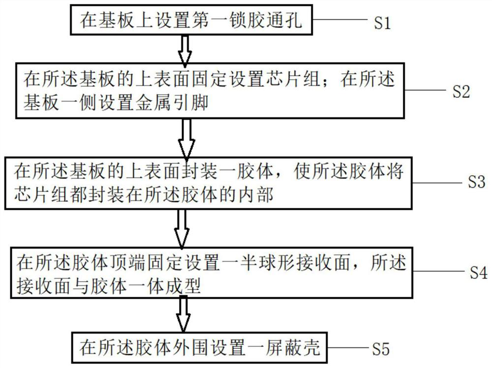
[0032] see figure 1 , the object of the present invention is to provide a kind of preparation technology of infrared receiver head for air conditioner with a large receiving angle, comprising the following steps:

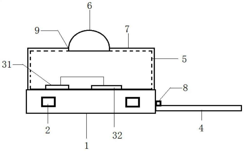
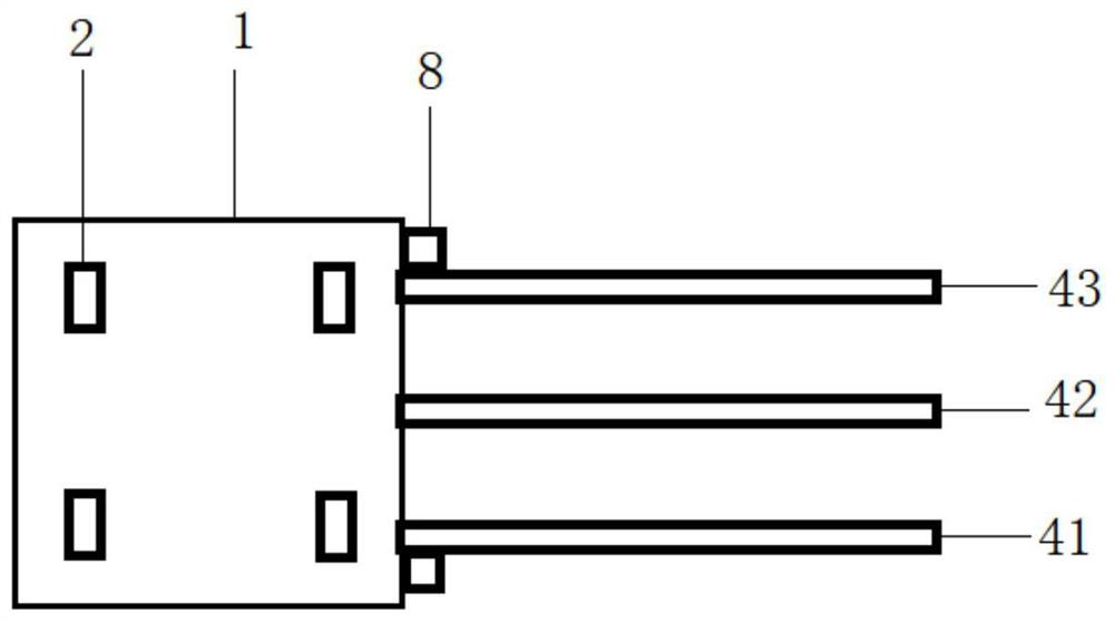
[0033] S1: set the first glue-locking through hole 2 on the substrate 1;

[0034] S2: The chip set 3 is fixedly arranged on the upper surface of the substrate 1; the metal pins 4 are arranged on one side of the substrate ...


PUM


Abstract

The invention discloses a preparation process of an infrared receiving head with a large receiving angle for an air conditioner. The preparation process comprises the following steps: forming a first glue locking through hole in a substrate; a chip set is fixedly arranged on the upper surface of the substrate; metal pins are arranged on one side of the substrate; packaging a colloid on the upper surface of the substrate; a semispherical receiving surface is fixedly arranged at the top end of the rubber body and is integrally formed with the rubber body; a shielding shell is arranged on the periphery of the colloid. The packaging glue can permeate into the glue locking through hole during packaging, so that the connection between the packaging layer and the substrate after the packaging glue is cured is firmer, the function failure of the infrared receiving head caused by looseness between the infrared receiving head and the packaging layer is prevented, the yield is improved, and the service life is prolonged; the hemispherical receiving surface is arranged, so that the receiving area is increased, the receiving angle is increased, and the receiving effect is better; and the shielding shell is arranged to shield interference signals, so that the anti-interference capability is enhanced, and the effects of large receiving angle, good receiving effect, strong anti-interference capability and high production efficiency are achieved.

Description

technical field [0001] The invention relates to the technical field of infrared receiving heads, in particular to a preparation process of an infrared receiving head for an air conditioner with a large receiving angle. Background technique [0002] In today's society, air conditioners have gradually become one of the household appliances that every household needs, and the normal use of air conditioners requires the installation of infrared receivers to receive infrared rays from the remote control and realize infrared remote control functions. At present, in the infrared receiving head of the prior art, the entire support is packaged by welding the infrared receiving device on the support. In the existing infrared receiving head bracket, after encapsulation, the connection between the bracket and the encapsulation layer is not reliable, and the bracket may become loose after a long time of use, leading to disconnection of the lead wire, which makes the infrared receiving he...

Claims


Application Information

Patent Timeline
Patent Type & Authority Applications(China)
IPC IPC(8): H01L21/50H01L21/56H01L23/552H01L25/16H01L23/31
CPCH01L21/50H01L21/56H01L25/167H01L23/552H01L23/3107
Inventor 徐代成
Owner 江苏国中芯半导体科技有限公司
Why Eureka
Try Eureka