Developer cartridge adapted to restrict leakage of developer
a technology of developer cartridges and cartridges, applied in the field of developer cartridges, can solve problems such as leakage outside the developer storing portion, and achieve the effect of restricting leakage of developers
- Summary
- Abstract
- Description
- Claims
- Application Information
AI Technical Summary
Benefits of technology
Problems solved by technology
Method used
Image
Examples
embodiment 1
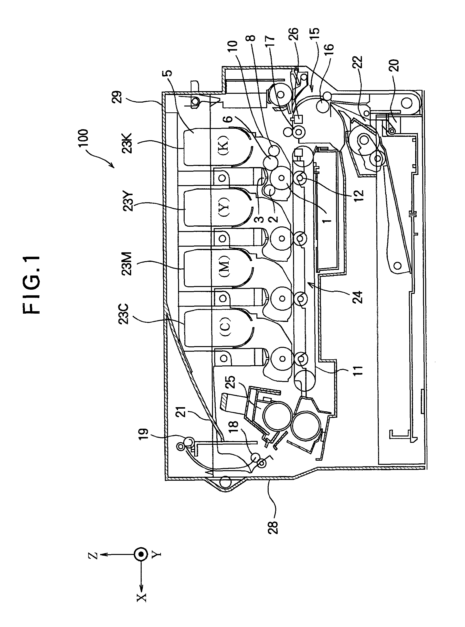
[0039]FIG. 1 is a schematic view showing an image forming apparatus using a toner cartridge according to Embodiment 1 of the present invention.
[0040]In FIG. 1, the image forming apparatus 100 has a configuration of a color electrophotographic printer capable of printing four colors, i.e., black (K), yellow (Y), magenta (M) and cyan (C).
[0041]The image forming apparatus 100 includes a lower frame 28 and an upper cover 29 constituting a casing of the image forming apparatus 100. A substantially S-shaped sheet feeding path 15 is defined in the lower frame 28. A sheet cassette 20 for storing recording sheets (i.e., recording medium) is disposed on the lower part of the lower frame 28, which corresponds to the upstream end of the sheet feeding path 15. A stacker 21 is disposed on the upper cover 29, which corresponds to the downstream end of the sheet feeding path 15.
[0042]A sheet pickup portion 22, a first feeding roller pair 16, a detecting portion 26, a second feeding roller pair 17, ...
embodiment 2
[0084]FIG. 17 shows a toner cartridge 85 according to Embodiment 2 of the present invention as seen in the same direction as FIG. 7. FIG. 18 is an enlarged view showing end portions of the toner cartridge 85 shown in FIG. 17. FIG. 19 shows an outer shape of a shutter 87 of the toner cartridge 85 as seen in the same direction as FIG. 10. FIG. 20 is a sectional view showing the toner cartridge 85 as seen in the same direction as FIG. 6.
[0085]The toner cartridge 85 of this embodiment is different from the toner cartridge 5 of Embodiment 1 (FIGS. 4 through 8) in shapes of the shutter 87 and the casing 81 (in particular, a part including a toner outlet opening 86). Therefore, components that are the same as those of the image forming apparatus 100 (FIG. 1) of Embodiment 1 are assigned the same reference numerals or omitted in figures, and duplicate description is omitted. The description herein is focused on the difference from Embodiment 1. The image forming apparatus of this embodiment...
embodiment 3
[0102]FIG. 23 shows a toner cartridge 95 according to Embodiment 3 of the present invention as seen in the same direction as FIG. 8. FIG. 24 shows the toner cartridge 95 of Embodiment 3 as seen in the same direction as FIG. 7. FIG. 25 shows a shutter 97 of the toner cartridge 95 of Embodiment 3 before a resilient seal member 38 is attached to the shutter 97 as seen in the same direction as FIG. 11. FIG. 26 shows the shutter 97 of the toner cartridge 95 of Embodiment 3 after the resilient seal member 38 is attached to the shutter 97 as seen in the same direction as FIG. 25. FIGS. 27 and 28 are sectional views showing the toner cartridge 95 of Embodiment 3 as seen in the same direction as FIG. 6.
[0103]The toner cartridge 95 of the image forming apparatus of this embodiment is different from the toner cartridge 5 of Embodiment 1 (FIGS. 4 through 8) in the shapes of the shutter 97 and the casing 91. Therefore, components that are the same as those of the image forming apparatus 100 (FIG...
PUM
 Abstract
Description
Claims
Application Information
 - R&D
- Intellectual Property
- Life Sciences
- Materials
- Tech Scout
- Unparalleled Data Quality
- Higher Quality Content
- 60% Fewer Hallucinations
Browse by: Latest US Patents, China's latest patents, Technical Efficacy Thesaurus, Application Domain, Technology Topic, Popular Technical Reports.
© 2025 PatSnap. All rights reserved.Legal|Privacy policy|Modern Slavery Act Transparency Statement|Sitemap|About US| Contact US: help@patsnap.com


