Device for closing containers with screw caps including quick change mechanism for closing element

a technology of screw cap and closing element, applied in the direction of caps, rotating screw stopper insertion, application, etc., can solve the problem of short set-up time, and achieve the effect of convenient rinse and cleaning

Active Publication Date: 2012-05-01
KRONES AG
View PDF12 Cites 11 Cited by
  • Summary
  • Abstract
  • Description
  • Claims
  • Application Information

AI Technical Summary

Benefits of technology

[0004]It is the object of the present disclosure to provide a device of the aforementioned type enabling a fast change of the closing element without disassembly of components adjoining the closing head, for instance a neck star or round guide plates.
[0005]The closing element is not directly held in the closing head, but in the quick-change mechanism, which is however configured such that the closing element is essentially perpendicular to the rotational axis of the closing head and can be laterally removed or inserted. Such a change can be carried out swiftly, resulting in a very short set-up time as no adjoining components have to be disassembled and then readjusted again. On the side of the closing head, and above the adjoining components, there is enough space for an easy manipulation. The quick-change mechanism can be used for different closing-head systems, e.g. both for plunger and stop systems, and can also be used for segmented closing elements.
[0006]In an expedient embodiment the respective closing element is held in a change member of the quick-change mechanism and is inserted or removed together with the change member. The change member is coupled in a force and motion transmitting manner via the positive coupling of the change member with the permanently fixed accommodating means remaining in the closing head. This positive coupling can be laterally disengaged for changing purposes and in the release state of the quick-change mechanism. An additional advantage is here that the thread in the closing head is no longer subject to wear because the accommodating means must be disassembled, if at all, only on rare occasions. The accommodating means of the change member can fit different screw caps. As an alternative, clearly different screw caps can belong to different change members.

Problems solved by technology

Such a change can be carried out swiftly, resulting in a very short set-up time as no adjoining components have to be disassembled and then readjusted again.

Method used


Image

  • Device for closing containers with screw caps including quick change mechanism for closing element
  • Device for closing containers with screw caps including quick change mechanism for closing element
  • Device for closing containers with screw caps including quick change mechanism for closing element

Examples


Embodiment Construction

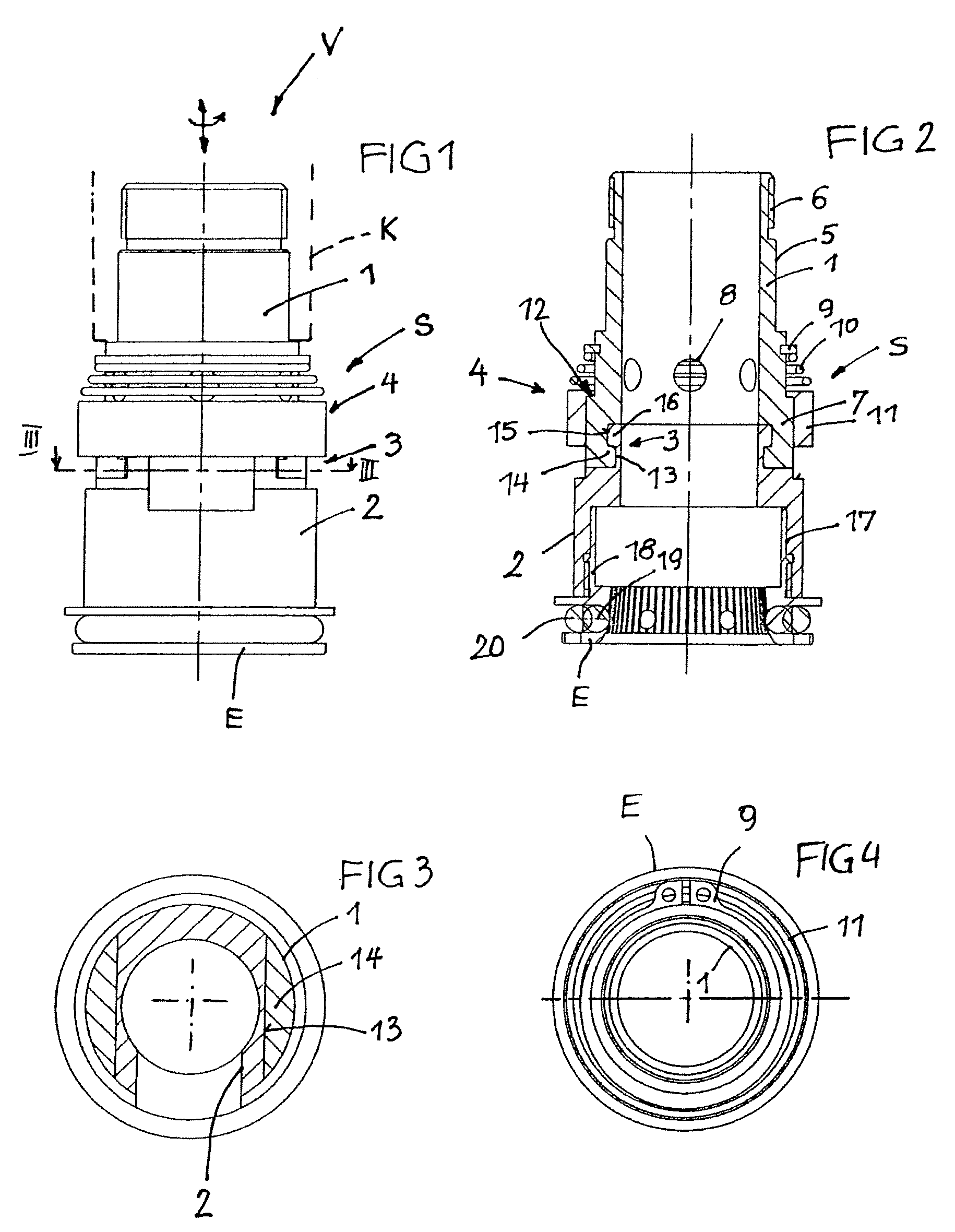
[0025]Of a device V for closing containers, for example PET bottles, in a closing device of a bottling system, FIG. 1 shows a lower part of a closing head K in broken line. The closing head K can be driven in axial direction and / or in rotational direction to mount a screw cap, which is positioned in a closing element E, on the external thread of the bottle neck of a bottle positioned underneath the closing head K. To position and convey the containers, components (not shown in FIG. 1) are provided next to the closing head and underneath said head.

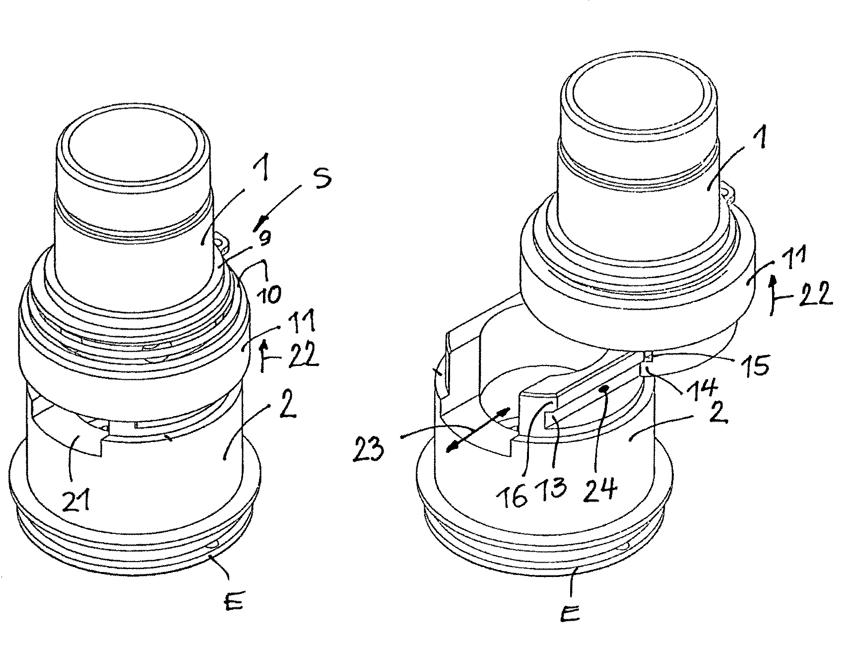
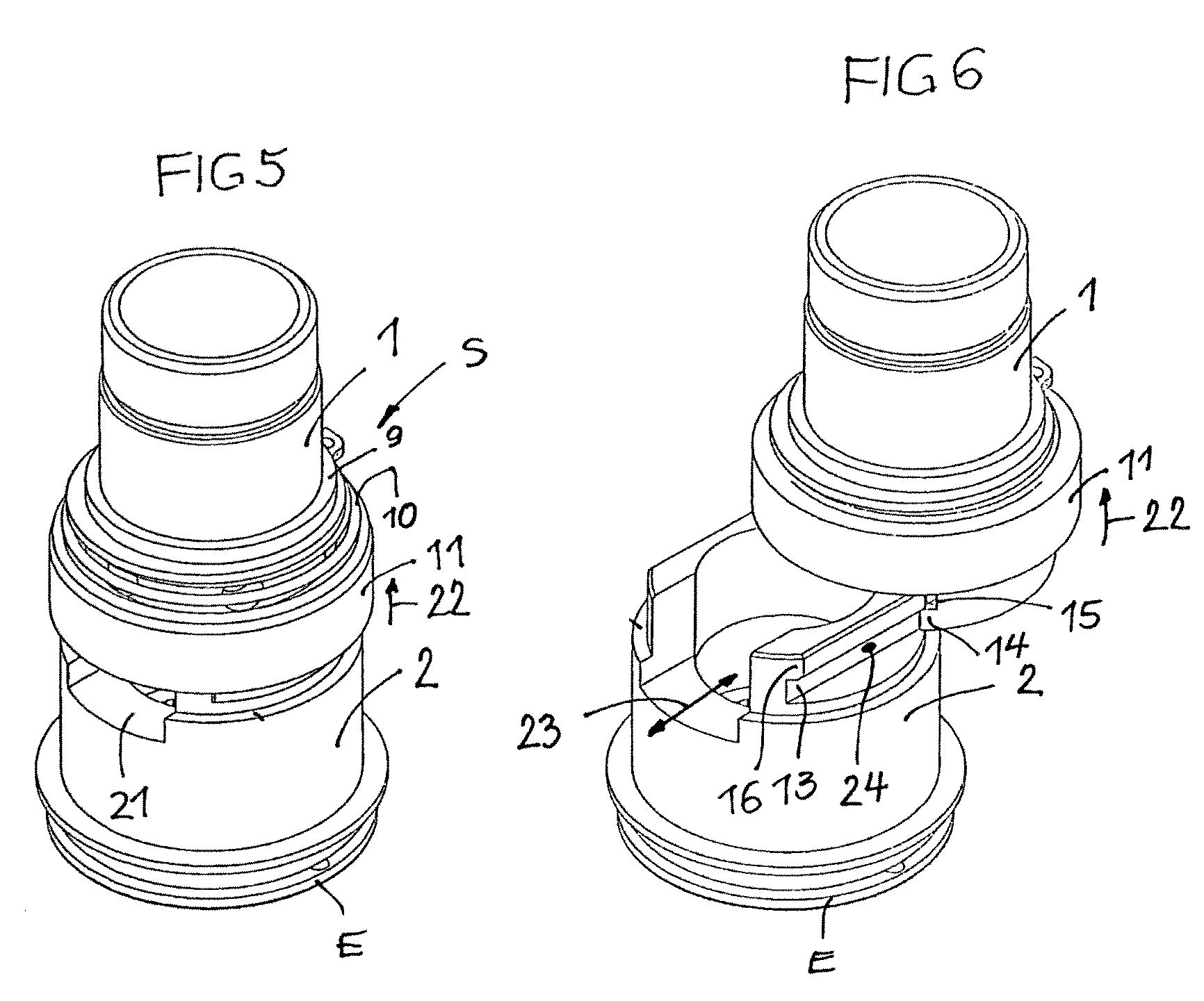
[0026]In FIG. 1 the closing head K is equipped with a quick-change mechanism S for exchangeably holding the respective closing element E. Main components of the quick-change mechanism S in FIG. 1 (see also FIG. 2 in a longitudinal section) are an accommodating means 1, a change member 2 in which the closing element E is held, a positive coupling 3 of the change member, and a change-member securing means 4. The quick-change mechanism S is pr...


PUM


Abstract

A device for closing containers, particularly bottles, with screw caps, having at least one rotatably drivable closing head in which a closure-specific closing element is exchangeably retained, a positive-fit quick-change mechanism for the respective closing element is embodied in the closing head, and in the release state of the quick-change mechanism the closing element can be laterally removed or inserted essentially perpendicular to the rotational axis of the closing head.

Description

CROSS-REFERENCE TO RELATED APPLICATION[0001]The present application claims the benefit of priority of International Patent Application No. PCT / EP2008 / 002603, filed Apr. 2, 2008, which application claims priority of German Patent Application No. 10 2007 028 429.4, filed Jun. 20, 2007. The entire text of the priority application is incorporated herein by reference in its entirety.FIELD OF THE DISCLOSURE[0002]The present disclosure relates to a device for application of screw cap enclosures, such as in beverage bottling operations.BACKGROUND[0003]In such devices that are used in practice, for instance for closing PET bottles with screw caps, for example, of the type known from DE-A-101 24 659, the closing element used must be screwed together with a fitting sleeve downwards out of the closing head upon change to another type of screw cap. Since different bottle conveying and treating components, e.g. round neck-guiding plates, of which at least some must be exactly adjusted to the clos...

Claims


Application Information

Patent Timeline
Patent Type & Authority Patents(United States)
IPC IPC(8): B67B3/20
CPCB67B3/2066B67B2201/10
Inventor SCHMATZ, STEFAN
Owner KRONES AG
Why Eureka
Try Eureka