Apparatus and method for conveyance and control of a high pressure hose in jet drilling operations

a technology of high-pressure hoses and hoses, which is applied in the direction of directional drilling, artificial islands, borehole/well accessories, etc., can solve the problems of limiting the depth at which the hose can be used, the prior approach using small-diameter flexible coiled tubing is limited, and the tubing strength is limited, so as to achieve the effect of convenient adjustment of the hose siz

Inactive Publication Date: 2012-05-01
FUTURE TECH LTD
View PDF12 Cites 17 Cited by
  • Summary
  • Abstract
  • Description
  • Claims
  • Application Information

AI Technical Summary

Benefits of technology

[0016]In a second, preferred embodiment, the tubing string is landed and held at the bottom of the workstring to trigger the HLSD and release the jetting hose, which begins jetting a lateral borehole as it is being extended from the tubing string (“pump and jet”). The tubing string is held in place as the high pressure fluid propels the jetting hose forward through the deflector shoe and jets a lateral wellbore in the surrounding formation, until the piston lands in the landing profile at the end of the tubing string. In this embodiment, the need for close control over the feed-in rate of the tubing string is eliminated from the lateral jetting operation, since the fluid pressure that extends the jetting hose also controls the speed of lateral borehole formation.
[0041]In one embodiment, the rate at which the jetting hose is extended from the tubing can be controlled so that the jetting hose is extended at substantially the same rate that it penetrates the formation, preferably by applying a counterbalancing fluid pressure on an upper portion of the jetting hose as the jetting hose is extended.

Problems solved by technology

This configuration results in a forward thrust on the nozzle, causing the nozzle to pull the hose behind it as the lateral borehole is created.
If the tubing string feed rate is too fast, the jetting nozzle path becomes erratic and the lateral borehole is not straight, too slow and the jetting nozzle creates a cavity behind itself resulting in the loss of forward thrust.
The prior approach using small diameter flexible coiled tubing is limited, however, in terms of depth, downhole inclination angles, utilization in flowing wells, and other areas.
The limited strength of the tubing limits the depths at which it can be used.
The angle of the wellbore across which the small diameter jetting hose can be used is limited by the hose's attachment to the end of the small diameter coiled tubing which, although more flexible than standard size coiled tubing, is limited to wellbore angles of around 30 degrees or less.
Specialized tube feeding units are required on the surface for the lateral jetting operation, since standard size coiled tube feeding units cannot be used with the small diameter tubing.
Other problems are created by the limitations of the small diameter flexible jetting hose itself that preclude it from being used without tubing to convey it downhole.
Small diameter flexible hose is limited in strength and cannot withstand significant tensile forces acting upon it, and is also limited in the length of flexible hose that can be lowered into a deviated main wellbore.
Small diameter flexible hose cannot be sealed around the outside of the hose at a grease injector to allow it to be used in conjunction with pressure seal equipment on the surface, thus precluding its use in flowing wells.
Small diameter flexible hose cannot be used in conjunction with an injector head on the surface that creates force to push the hose into, or, alternately, pull the hose out of, an oil or gas well, since the hose is so flexible that it cannot be easily pushed downward.
Still another problem with prior apparatus and methods used to form lateral boreholes with a jetting hose lowered with small diameter coiled tubing is that success is greatly dependent on the skill of the operator in charge of the installation.
Using standard sized coiled tubing would allow the jetting hose to be employed at greater depths, higher inclination angles, and in flowing well applications, but would make it significantly more difficult to control the tubing feed rate relative to jetting nozzle progress during lateral borehole formation using standard weight versus pressure comparisons.
For example, the weight gauges for standard coiled tubing are typically in 100-lb to 200-lb increments, and so are simply not sensitive enough to use the hanging weight of the tubing as a benchmark for comparison to the feed-in rate and pressure drop.
Accordingly, even a skilled operator would find it impractical to use the usual weight measurements to control the feed-in rate of the jetting hose using standard coiled tubing.
Standard coiled tubing is also limited in the bending radius that it can traverse, which does not allow its use for some jetting operations.
Conventional jointed pipe also requires a significant amount of time to connect the joints together, which is particularly worrisome when inserting and removing the pipe sections from a well drilled for producing hydrocarbons, since it results in great operating expense due to costs related to labor, rig rental, and other factors known to those skilled in the art.

Method used


Image

  • Apparatus and method for conveyance and control of a high pressure hose in jet drilling operations
  • Apparatus and method for conveyance and control of a high pressure hose in jet drilling operations
  • Apparatus and method for conveyance and control of a high pressure hose in jet drilling operations

Examples


Embodiment Construction

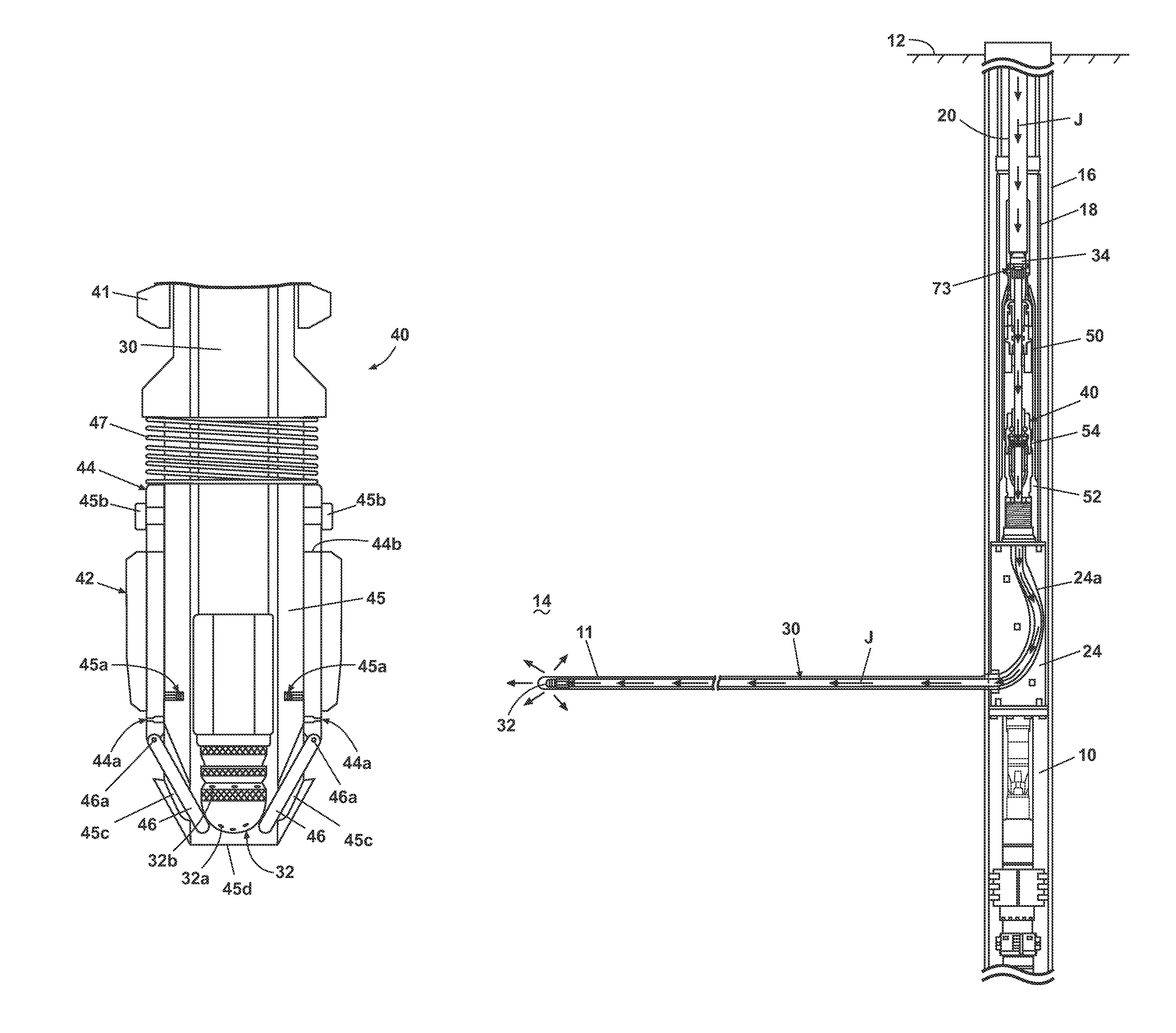
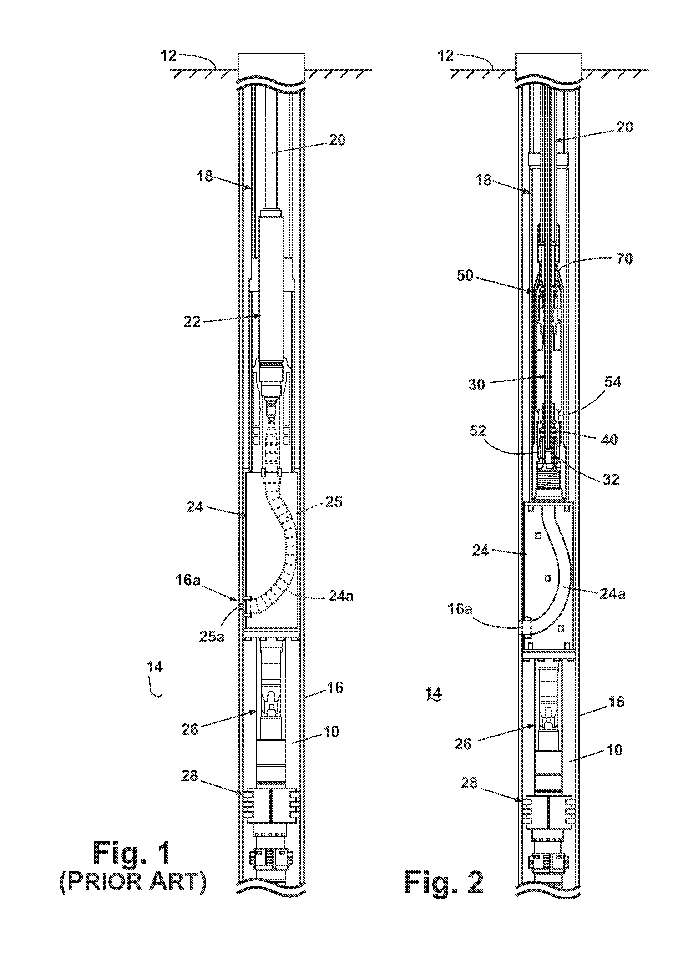
[0064]FIG. 1 shows a prior assembly used for cutting lateral openings in the casing 16 of a vertical wellbore 10, and for subsequently redirecting a jetting hose out through the openings to jet lateral boreholes in formation 14. In general, the assembly includes a deflector shoe 24 supported at or near the bottom of the workstring, for example secured to the end of the workstring (“production”) tubing 18, and a flexible linked cutting tool 25 rotatably driven by a mud motor 22 lowered on the end of standard tubing string 20. Cutting tool 25 is selectively extended through a channel 24a in deflector 24 to place cutting head 25a in contact with the wellbore casing 16, forming lateral openings 16a for entry of a jetting hose into the surrounding formation 14 in known manner. The vertical and rotational positioning of deflector shoe 24, and thus of the cutting tool 25 and the location of the lateral holes 16a that it forms, is determined by an indexer device 26. The assembly is locked i...


PUM


Abstract

A jetting hose is conveyed downhole retracted within a tubing string for jetting lateral boreholes from a main wellbore, is released at the jetting depth and pumped from the tubing string and into a lateral borehole with jetting fluid. A piston is secured to the upper end of the jetting hose, and the pumped jetting fluid drives the piston. A speed control regulates the penetration rate of the jetting hose into the formation independent of the tubing string weight.

Description

CROSS-REFERENCE TO RELATED APPLICATIONS[0001]This application is related to and claims priority of U.S. Provisional Application No. 60 / 999,705 by the same inventors (Brunet and Bouchard) filed Oct. 22, 2007, the disclosure of which is incorporated herein by reference in its entirety.BACKGROUND OF THE INVENTION[0002]1. Field of the Invention[0003]The invention relates to apparatus and methods for drilling lateral boreholes from a main wellbore using a high pressure jetting hose for hydrocarbon recovery. In one of its aspects, the invention relates to a method and system for controlling the rate at which a lateral bore hole is drilled by jetting a fluid at high pressure into the formation. In another of its aspects, the invention relates to a method and system for conveying a high pressure jetting hose into a main well bore for later drilling into a producing formation.[0004]2. Description of Related Art[0005]The creation of lateral (also known as “radial”) boreholes in oil and gas we...

Claims


Application Information

Patent Timeline
Patent Type & Authority Patents(United States)
IPC IPC(8): E21B7/18
CPCE21B7/18E21B41/0035
Inventor BRUNET, CHARLESBOUCHARD, MICHEL
Owner FUTURE TECH LTD
Why Eureka
Try Eureka