Solar tracking device

a tracking device and solar energy technology, applied in the direction of instruments, instruments, instruments for comonautical navigation, etc., can solve the problems that most prior art solar collection devices cannot achieve these limits fully, and no prior art solar collection devices can achieve them

Inactive Publication Date: 2012-05-01
CONCRETE SYST
View PDF24 Cites 25 Cited by
  • Summary
  • Abstract
  • Description
  • Claims
  • Application Information

AI Technical Summary

Problems solved by technology

Most prior art devices cannot fully achieve these limits and are thus defective in getting the best out of the device itself.
No prior art solar...

Method used


Image

  • Solar tracking device
  • Solar tracking device
  • Solar tracking device

Examples


Embodiment Construction

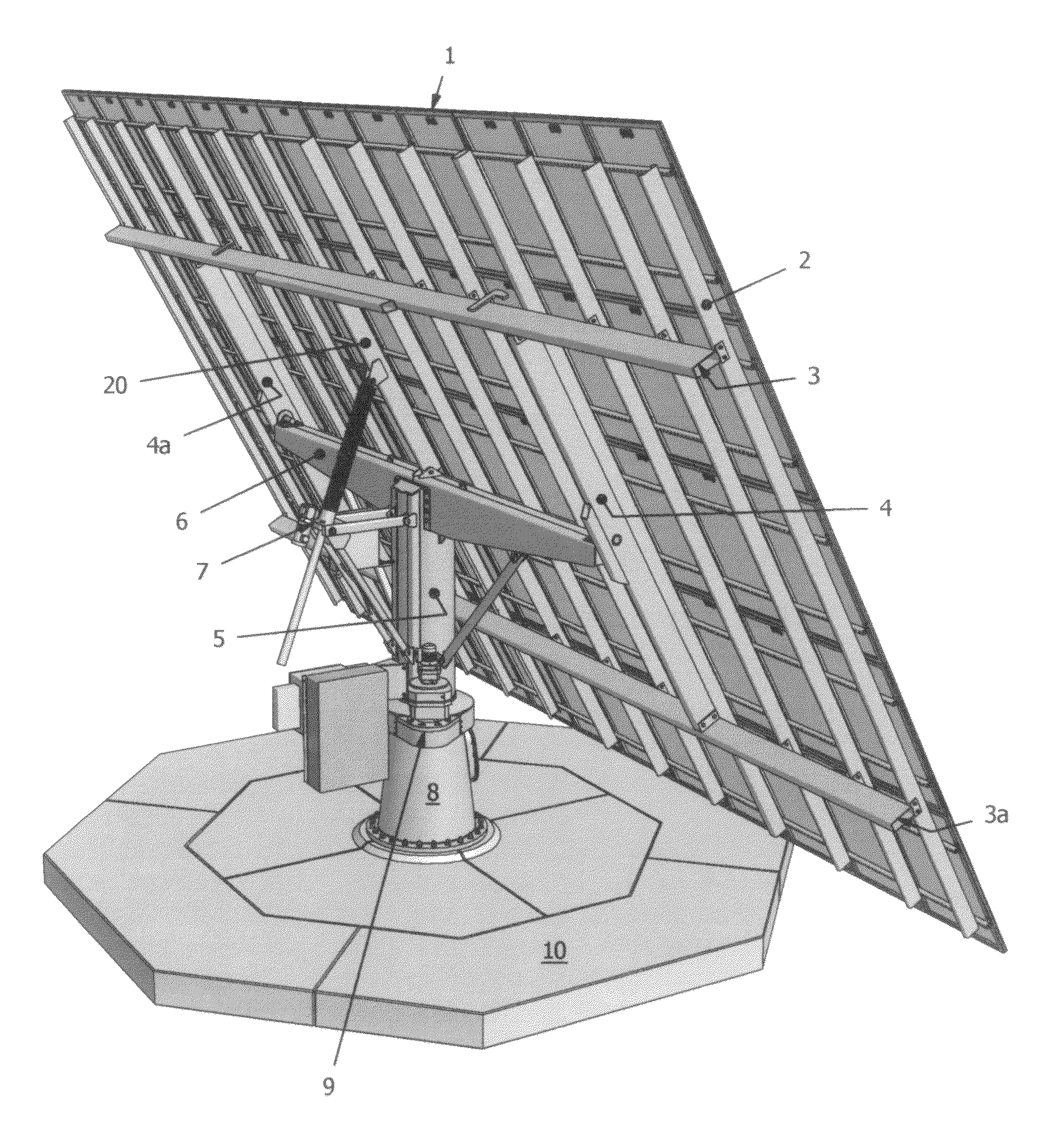
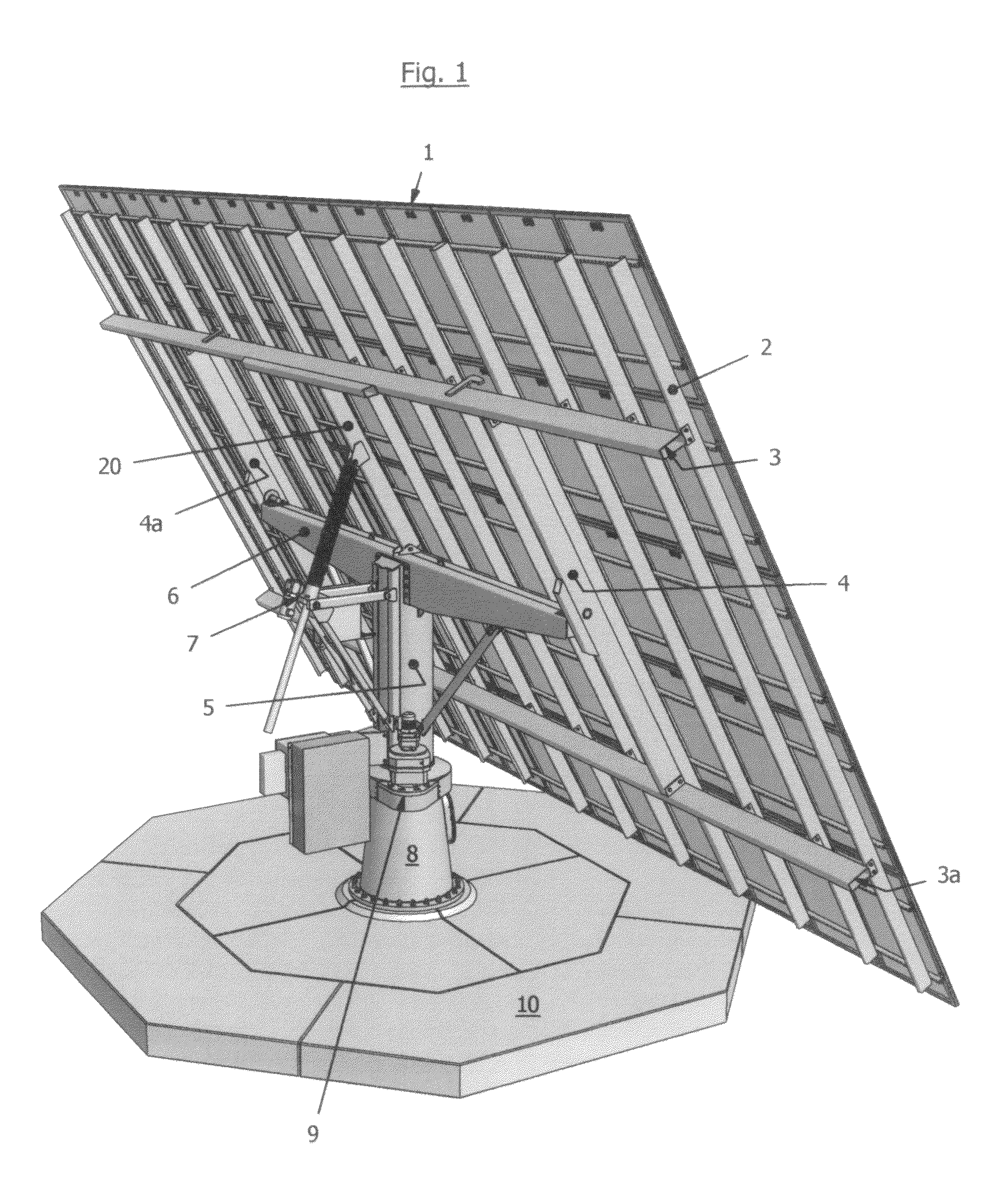
[0022]Looking now specifically at the drawings, which are a purported best mode of this invention at the time of filing, but to which the inventor does not feel limited by, FIG. 1 is a perspective view of a typical solar panel device of this invention from the back side thereof. In this FIG. 1 is the solar array made up of a number of solar panels joined together. Electrical elements will adjoin all of these panels and will flow downwardly (not shown in the figure). The array is supported by a number of transversal beams, one of which is shown as 2. Two larger longitudinal beams are shown as 3 and 3a and another pair of cross beams as 4 and 4a. An upper rotatable column is shown as 5 and this is movably connected to cross supports 4 and 4a via main beam 6. The panel tilting device is shown as 7. Upper rotatable column 5 is connected to the lower column 8 at movable joint 9 and is further firmly attached to the base support 10.

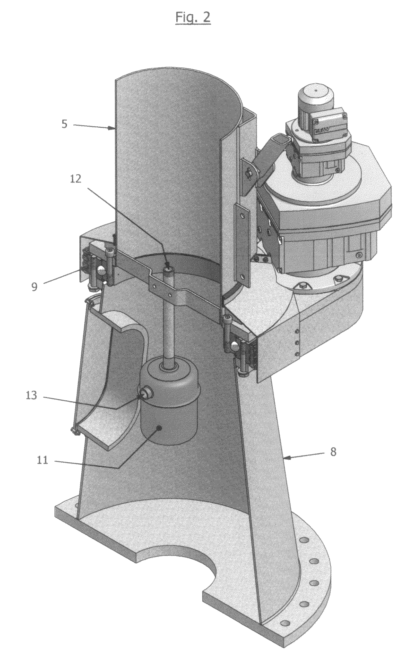
[0023]FIG. 2 is a cut-away view of the lower column as it...


PUM


Abstract

A dual axis tracker is a solar collecting device with fully mobile panel arrays that can be fully rotated 360° and tilted from a 90° position to a 10° position relative to the earth and is easy to maintain and operate. This device has a base support followed by a stable lower column attached thereto and a movable or rotatable upper column that permits full rotation located thereon. This permits the full rotation. A motorized jack is employed to tilt the panel array from the 90° position to a 10°. Since the array is held higher off the ground by a longer lower column, such vertical positioning is achieved in a better manner than prior art devices. Because of these movements more power can be produced in a given amount of time than prior art devices. In addition, during periods of snowfall, this device can collect more radiation off the accumulated snow cover that will surround the device thus taking advantage of said radiation to produce even greater power than previously possible.

Description

CROSS REFERENCES TO RELATED APPLICATIONS[0001]This application is related to my previously filed patent application AT-100-A, Ser. No. 12 / 590,749, filed Nov. 16, 2009BACKGROUND OF THE INVENTION[0002]1. Field of the Invention[0003]This application relates to the field of solar tracking devices and more specifically to dual axis solar tracking devices that are employed in the generation of electrical energy. Even more specifically, this invention is related to dual axis solar tracking devices that can be easily deployed and have an excellent ability to track the sun in order to produce green energy therefrom.[0004]2. Description of the Prior Art[0005]Since there has been available technology, there has been an effort to harness the energy that is produced on a daily basis by the sun. Well known among these efforts is a means of producing electrical energy using solar devices that employ solar collection devices of well-known materials that collect the sun's energy. These collection el...

Claims


Application Information

Patent Timeline
IPC IPC(8): G01J1/20F24J2/40B66F3/24
CPCF24J2/542Y02E10/47F24J2002/5458F24J2002/5482F24S30/452F24S2030/133F24S2030/15H02S20/30Y02E10/50
Inventor THEL, ANTON BOGDAN
Owner CONCRETE SYST
Why Eureka
Try Eureka