
Active current limiting circuit and power regulator using the same

a current limiting circuit and active current technology, applied in the direction of electric variable regulation, process and machine control, instruments, etc., can solve the problems of affecting the accuracy of the current limiting circuit, the minimum dropout voltage between the input side and the output side of the voltage regulator will be enlarged, etc., to achieve low process and temperature variation and high accuracy

Active Publication Date: 2012-05-01
HOLTEK SEMICON
View PDF7 Cites 25 Cited by
  • Summary
  • Abstract
  • Description
  • Claims
  • Application Information

AI Technical Summary

Benefits of technology

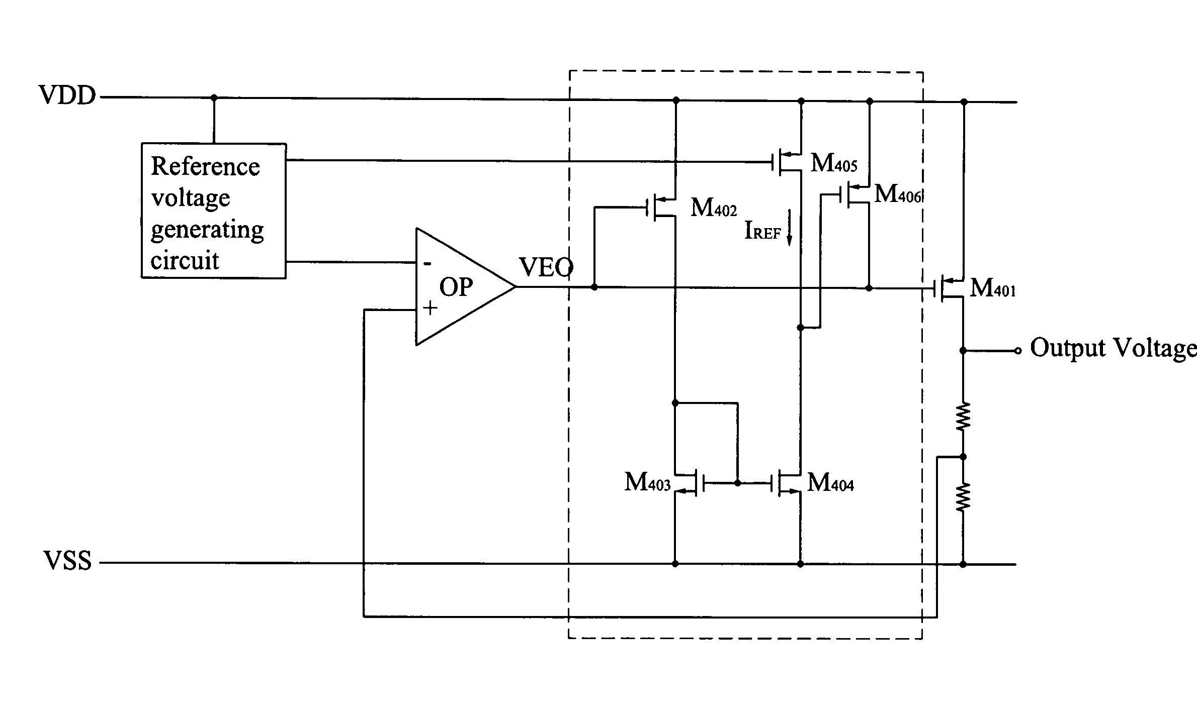
[0009]In view of the disadvantages of prior art, the primary object of the present invention relates to an active current limiting circuit and a power regulator using the same and the method thereof, which takes advantage of active components to form a feedback circuit so as to achieve the goal of high accuracy for low process and temperature variation.

Problems solved by technology

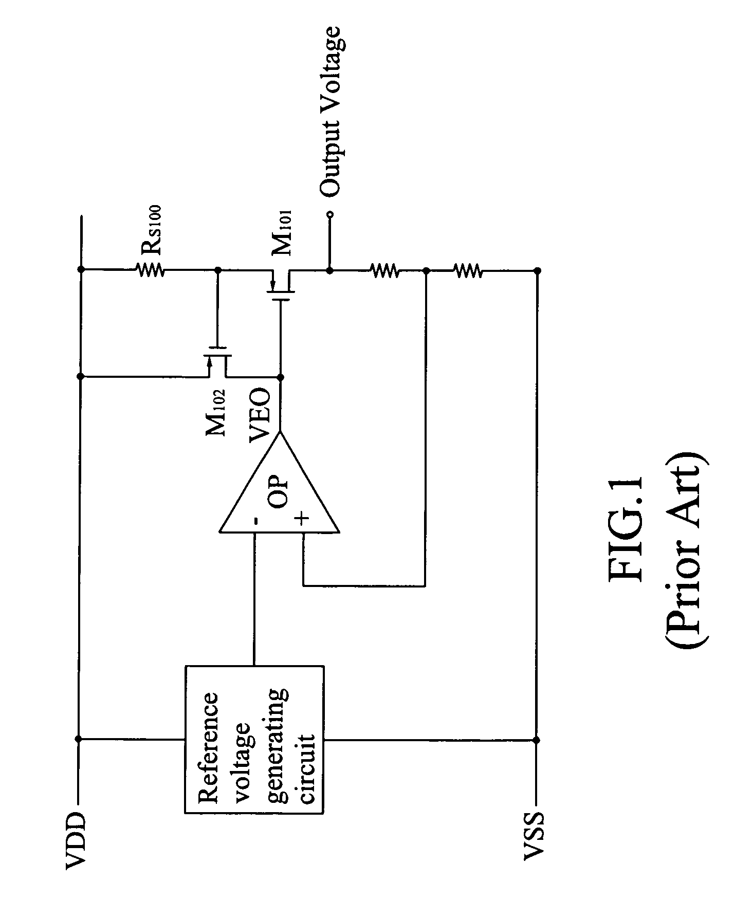
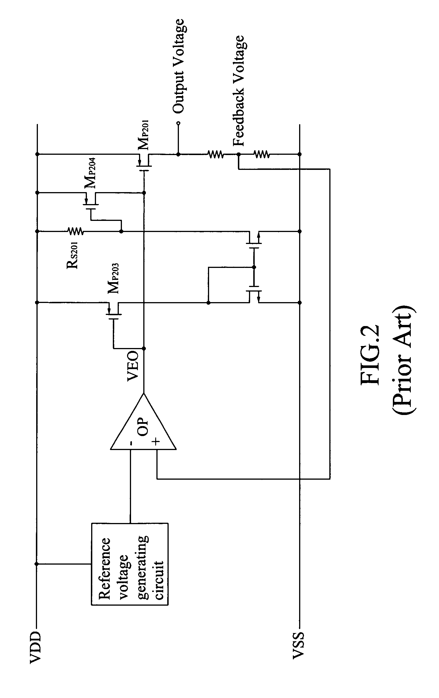
However, the most significant drawback for this approach is the minimum dropout voltage between the input side and output side of the voltage regulator will be enlarged.
However, the error caused by said resistor RS201 for process and temperature variation will directly affect the accuracy of the current limiting circuit.

Method used


Image

  • Active current limiting circuit and power regulator using the same
  • Active current limiting circuit and power regulator using the same
  • Active current limiting circuit and power regulator using the same

Examples


Embodiment Construction

[0034]The following descriptions are of exemplary embodiments only, and are not intended to limit the scope, applicability, or configuration of the invention in any way. Rather, the following description provides a convenient illustration for implementing exemplary embodiments of the invention. Various changes to the described embodiments may be made in the function and arrangement of the elements described. For your esteemed members of reviewing committee to further understand and recognize the fulfilled functions and structural characteristics of the invention, several exemplary embodiments cooperating with detailed description are presented as the follows.

[0035]Refer to FIG. 3 now, which relates to a current limiting method for a power regulator, comprising:[0036](a) start;[0037](b) the power regulator provides a constant voltage at normal stable voltage situation and a power transistor inside the power regulator provides a current to a loading;[0038](c) sense an output current o...


PUM


Abstract

The present invention mainly relates to a current limiting circuit, also known as over-current protection circuit, and a power regulator using the same. The purpose for the circuit is to protect the power device and the loading circuit for the power regulator. The conventional current limiting circuit takes advantage of a resistor and a MOS to convert the detected over current into a voltage and then turn on a P-typed MOS to clamp the gate voltage of a power transistor so as to achieve the goal of current limiting. However, the process variation for the resistor and said MOS and their temperature variation lead to a significant error to the limiting current. The present invention, therefore, takes advantage of the current comparison to enhance the accuracy for the current limiting circuit.

Description

BACKGROUND OF THE INVENTION[0001]1. Field of the Invention[0002]The present invention relates to a current limiting circuit and a power regulator using the same, more particularly to, an active current limiting circuit and a power regulator using the same.[0003]2. Description of the Prior Arts[0004]Generally speaking, in the application for DC voltage regulators (Also known as “power regulator”), there will always be some corresponding protection circuits such as over voltage protection, over temperature protection, and over current protection, and said over current protection can be realized by a current limiting circuit. In the most of occasions, the current limiting mechanism takes advantage of the detection of the current running through the power transistor, and a resistor is used to convert the detected current into the voltage, and then the voltage turns on a P-typed transistor so as to clamp the gate voltage of said power transistor by a charging current. Thus, the loading c...

Claims


Application Information

Patent Timeline
Patent Type & Authority Patents(United States)
IPC IPC(8): G05F1/618G05F1/573
CPCG05F1/573
Inventor JIAN, MING-HONG
Owner HOLTEK SEMICON
Learn More