Endoscope system

a technology of endoscope and endoscope, which is applied in the field of endoscope system, can solve the problems of taking time to position the optical filter, and the inability to obtain rgb image based on white light illumination,

Active Publication Date: 2012-05-01
HOYA CORP
View PDF19 Cites 6 Cited by
  • Summary
  • Abstract
  • Description
  • Claims
  • Application Information

AI Technical Summary

Benefits of technology

[0009]Therefore, an object of the present invention is to provide an endoscope system that outputs an image based on white light and another image based on the predetermined wavelength range light simultaneously, or that is capable of rapidly switching between the display of an image based on white light and the display of an image based on the predetermined wavelength range light.

Problems solved by technology

However, it takes time to position the optical filter.
Furthermore, when an optical filter is used, an RGB image based on white light illumination can not be obtained.

Method used


Image

  • Endoscope system
  • Endoscope system
  • Endoscope system

Examples


first embodiment

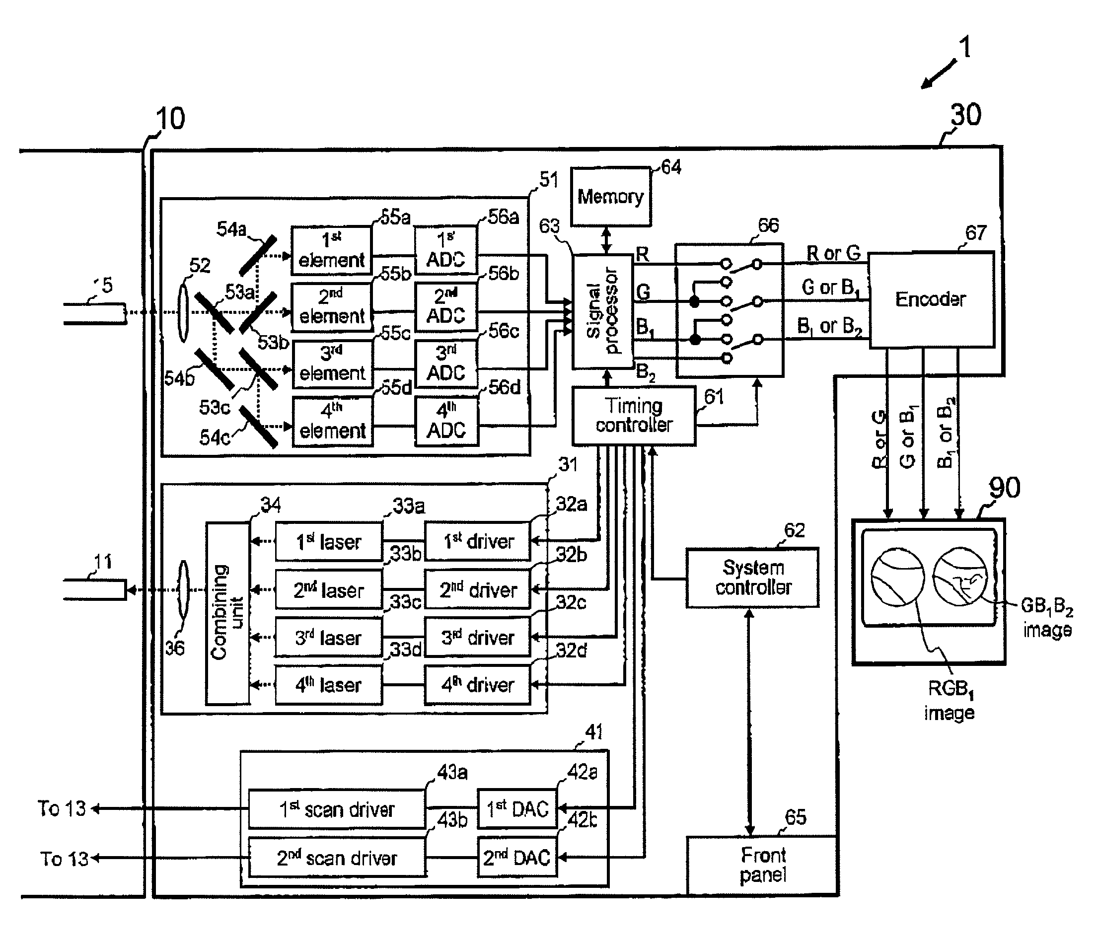
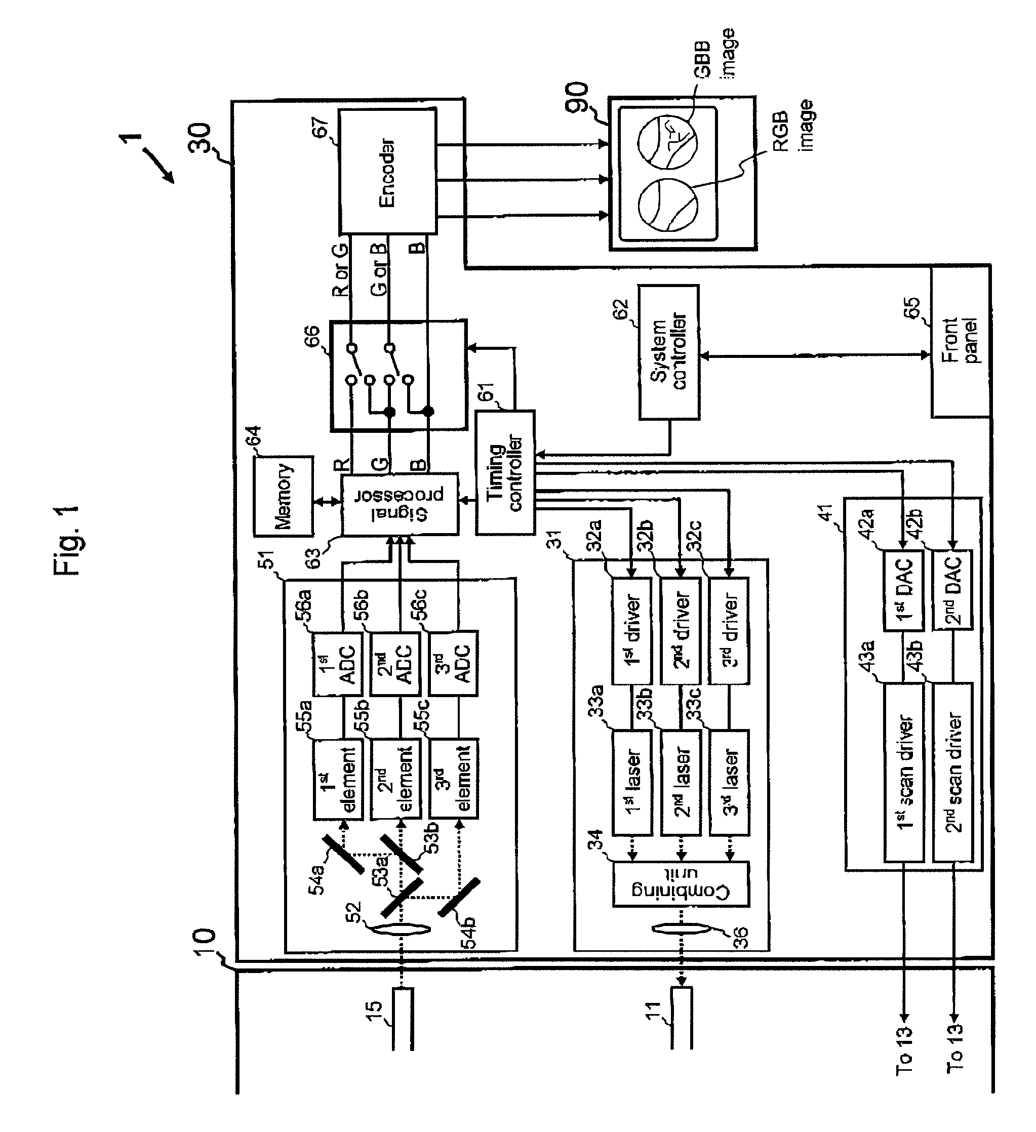
[0021]The present invention is described below with reference to the embodiments shown in the drawings (FIGS. 1 to 6). As shown in FIG. 1, an endoscope system 1 in the first embodiment is a full-color scanning fiber endoscope and comprises a probe 10, a processor 30, and a display 90.

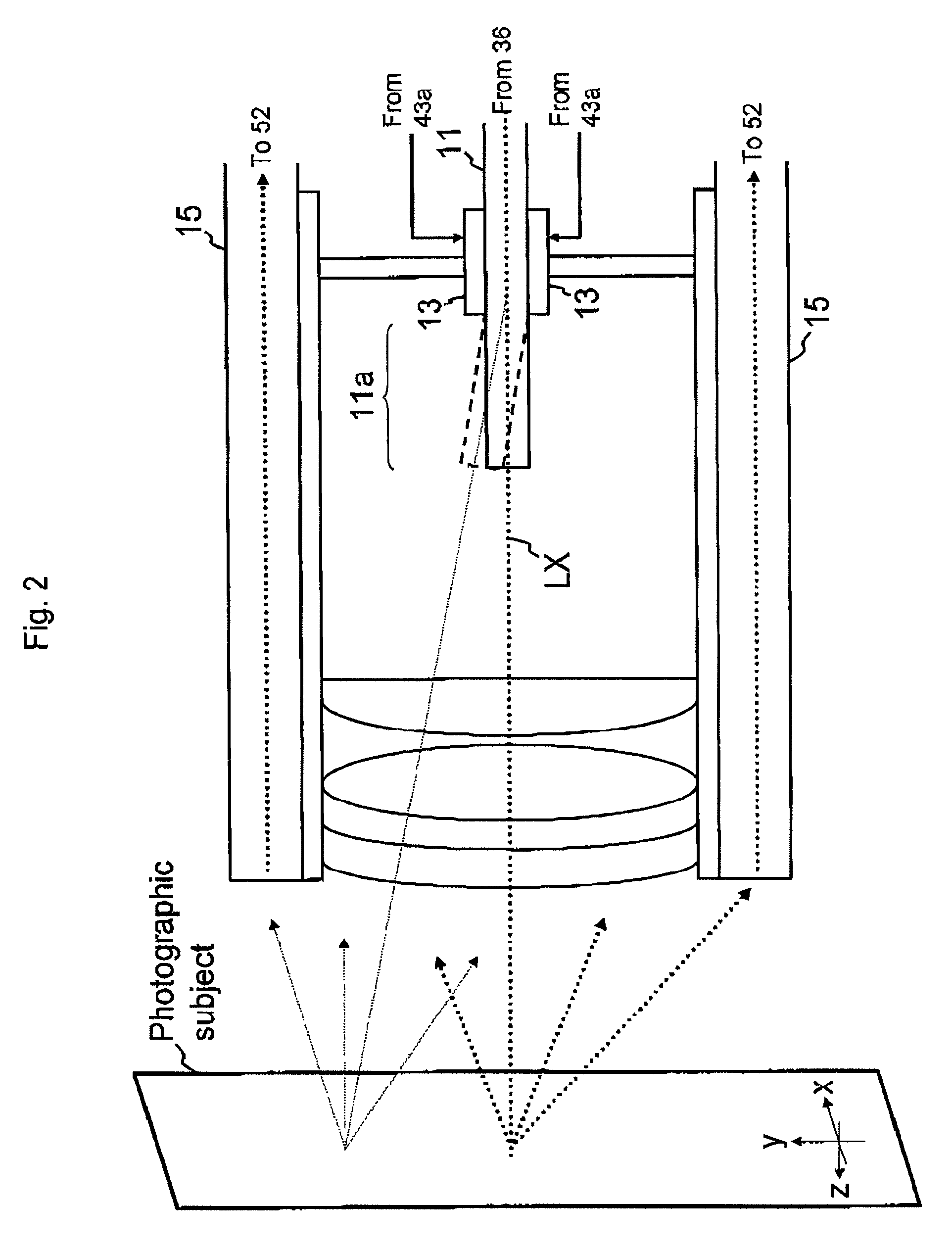
[0022]By way of orientation, in the first and second embodiments, direction x, direction y, and direction z are defined (see FIG. 2). Direction x is the direction perpendicular to the optical axis LX. Direction y is the direction perpendicular to the optical axis LX and direction x. Direction z is the direction parallel to the optical axis LX and perpendicular to both direction x and direction y.

[0023]The optical axis LX is the optical axis of an inflexible part of the fiber 11 which is used for illuminating. The inflexible part is not moved or twisted by the scan unit 13, and is arranged at the near side of bendable part of the tip 11a of the fiber 11.

[0024]The probe 10 has a fiber 11 for illuminating,...

second embodiment

[0091]Next, the second embodiment is explained (see FIGS. 8 and 9).

[0092]In the first embodiment, the blue signal that is output to the green channel and the blue channel of the encoder 67 includes the same light at the third wavelength range, in order to display the GBB image.

[0093]However, in the second embodiment, the wavelength range of the light included in the blue signal that is output to the green channel of the encoder 67 is different from that in the blue signal that is output to the blue channel of the encoder 67, in order to display the GB1B2 image. The points that differ from the first embodiment are explained next.

[0094]In the second embodiment, the light source 31 has a first driver 32a, a second driver 32b, a third driver 32c, a fourth driver 32d, a first laser 33a, a second laser 33b, a third laser 33c, a fourth laser 33d, a combining unit 34, and a first condenser lens 36 for illuminating.

[0095]The first laser 33a is a red light laser diode, and emits light in a fi...


PUM


Abstract

An endoscope system comprises a light source, a light sensor, a signal processor, a video-signal generator, and a switcher. The light source emits red light including a first wavelength, green light including a second wavelength, and blue light including a third wavelength. The light sensor receives the light of the light source. The signal processor obtains a red signal based on the red light, a green signal based on the green light, and a blue signal based on the blue light. The video-signal generator generates video signal based on the red, green, and blue signals. The switcher switches between a first switching state and a second switching state. The red, green, and blue signals are output to the video-signal generator in the first switching state. The green and blue signals are output to the video-signal generator in the second switching state.

Description

BACKGROUND OF THE INVENTION[0001]1. Field of the Invention[0002]The present invention relates to an endoscope system that displays an image based on light including a predetermined wavelength range.[0003]2. Description of the Related Art[0004]An endoscope system that displays an image based on light including a predetermined wavelength range has previously been proposed.[0005]Because the depth from the surface of the tissue from which light is reflected varies according to the wavelength of the illumination light, the desired imaging depth can be adjusted by proper choice of wavelength.[0006]Japanese unexamined patent publication (KOKAI) No. 2002-34908 discloses an endoscope system that displays an image based on light including a predetermined wavelength, by arranging an optical filter that transmits only light of the predetermined wavelength range in the optical path.[0007]However, it takes time to position the optical filter.[0008]Furthermore, when an optical filter is used, an R...

Claims


Application Information

Patent Timeline
Patent Type & Authority Patents(United States)
IPC IPC(8): H04N13/00
CPCA61B1/0638A61B5/02007H04N5/2256H04N5/232H04N9/045H04N9/097A61B1/00172A61B1/063A61B1/07A61B5/1455H04N2005/2255H04N2209/049A61B1/0655H04N23/555H04N23/56H04N23/633H04N23/84H04N23/16
Inventor IKETANI, KOHEISUGIMOTO, HIDEO
Owner HOYA CORP
Why Eureka
Try Eureka